ProbeStudy No. 01: Line-to-Ground Probing | Why Is It Critical in Troubleshooting?
The meter said 'safe.' It was lying. Here's what saved my life.
The Setup
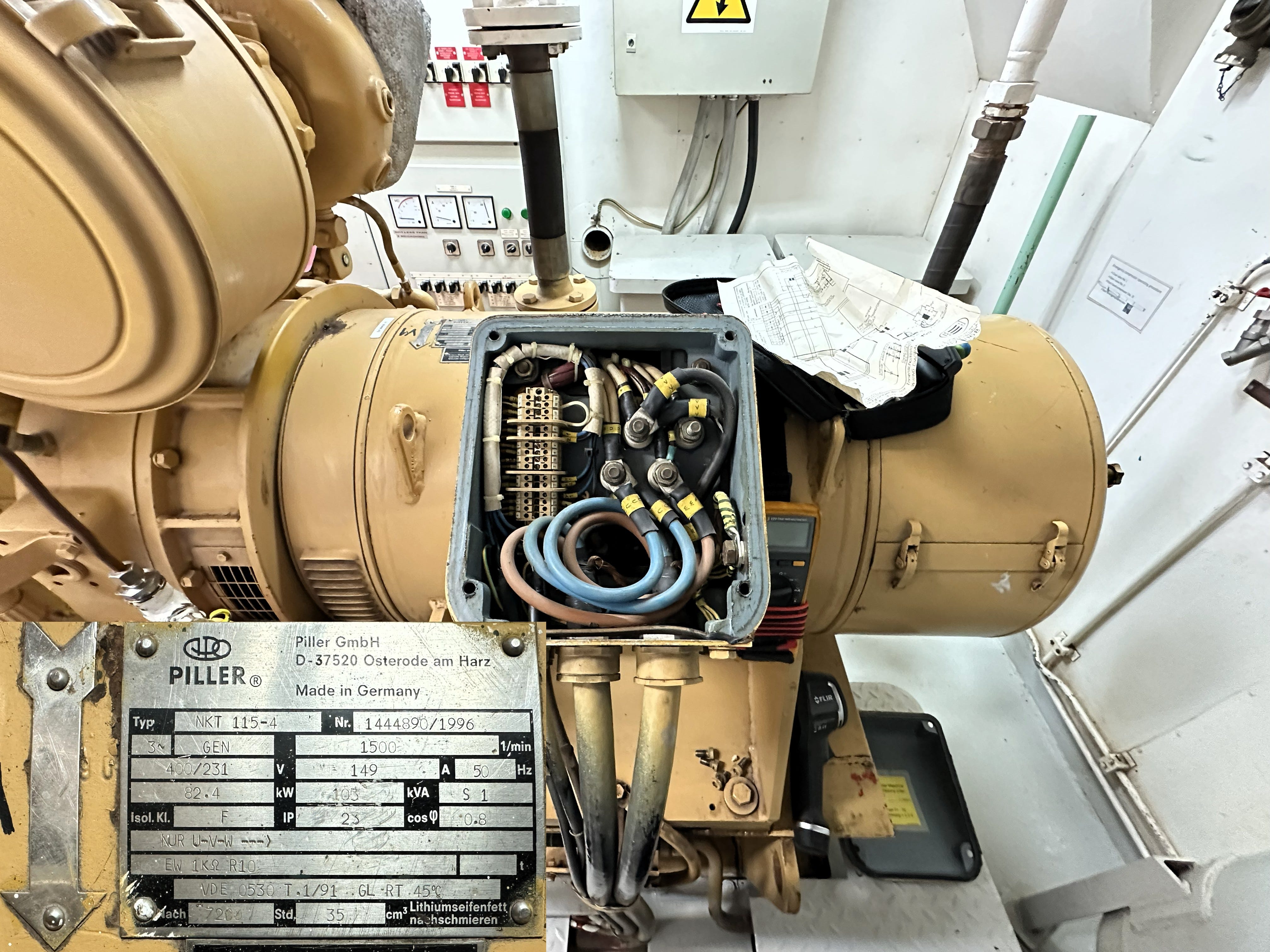
It was a routine TEK2 inspection. Emergency generator winding space heater wasn’t producing heat.
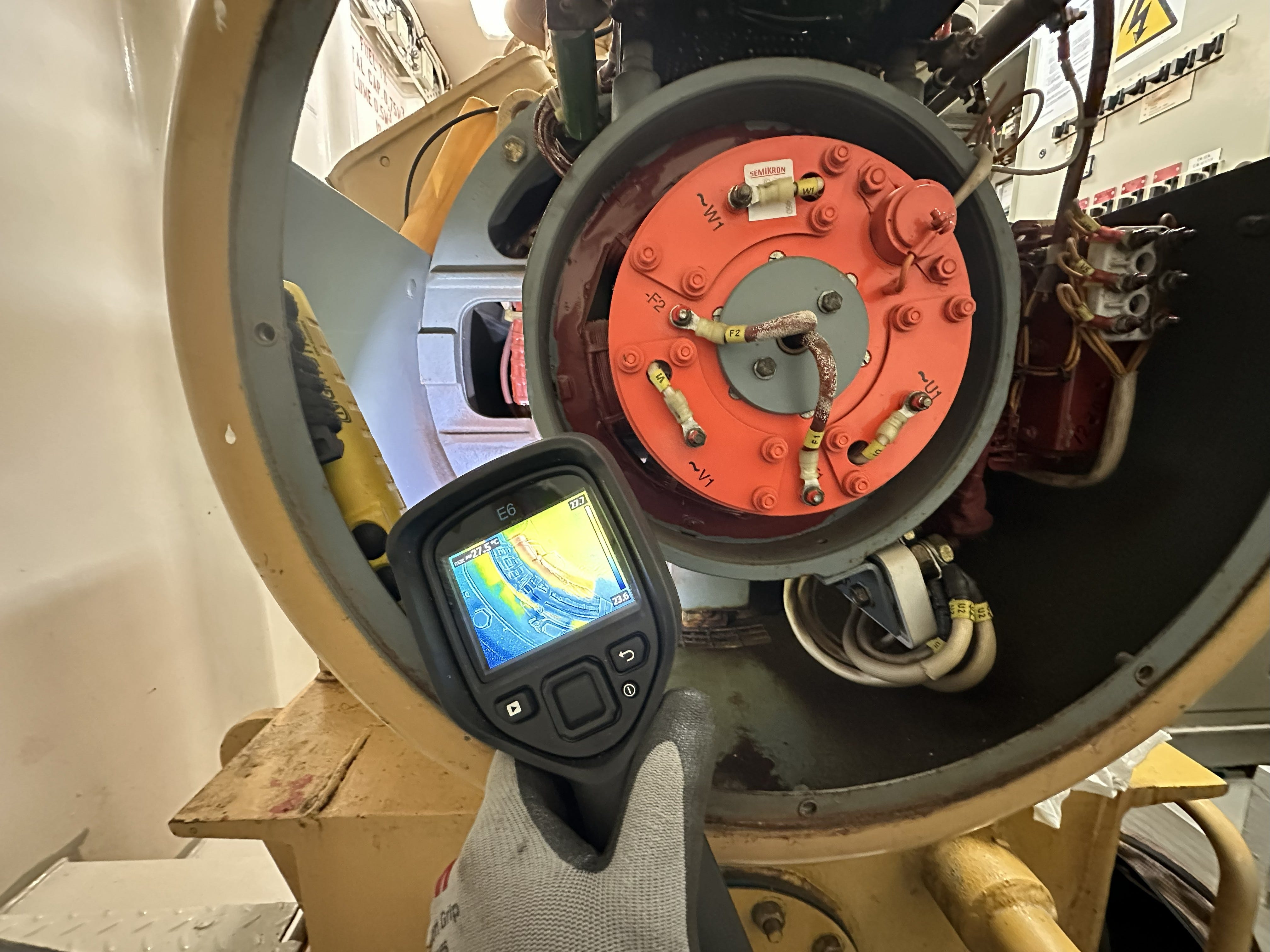
Standard maintenance procedure: verify the heating element is producing heat. Space heaters are critical for preventing moisture buildup in generator windings during standby periods. A non-functional heater can lead to insulation degradation, reduced dielectric strength, and potential winding failure—especially problematic for emergency equipment that must be ready on demand.
Thanks for reading ProbeLem Publication! Subscribe for free to receive new posts and support my work.
I pulled out my multimeter and measured line-to-line voltage at the heater terminals.
The reading: 14.6mV AC
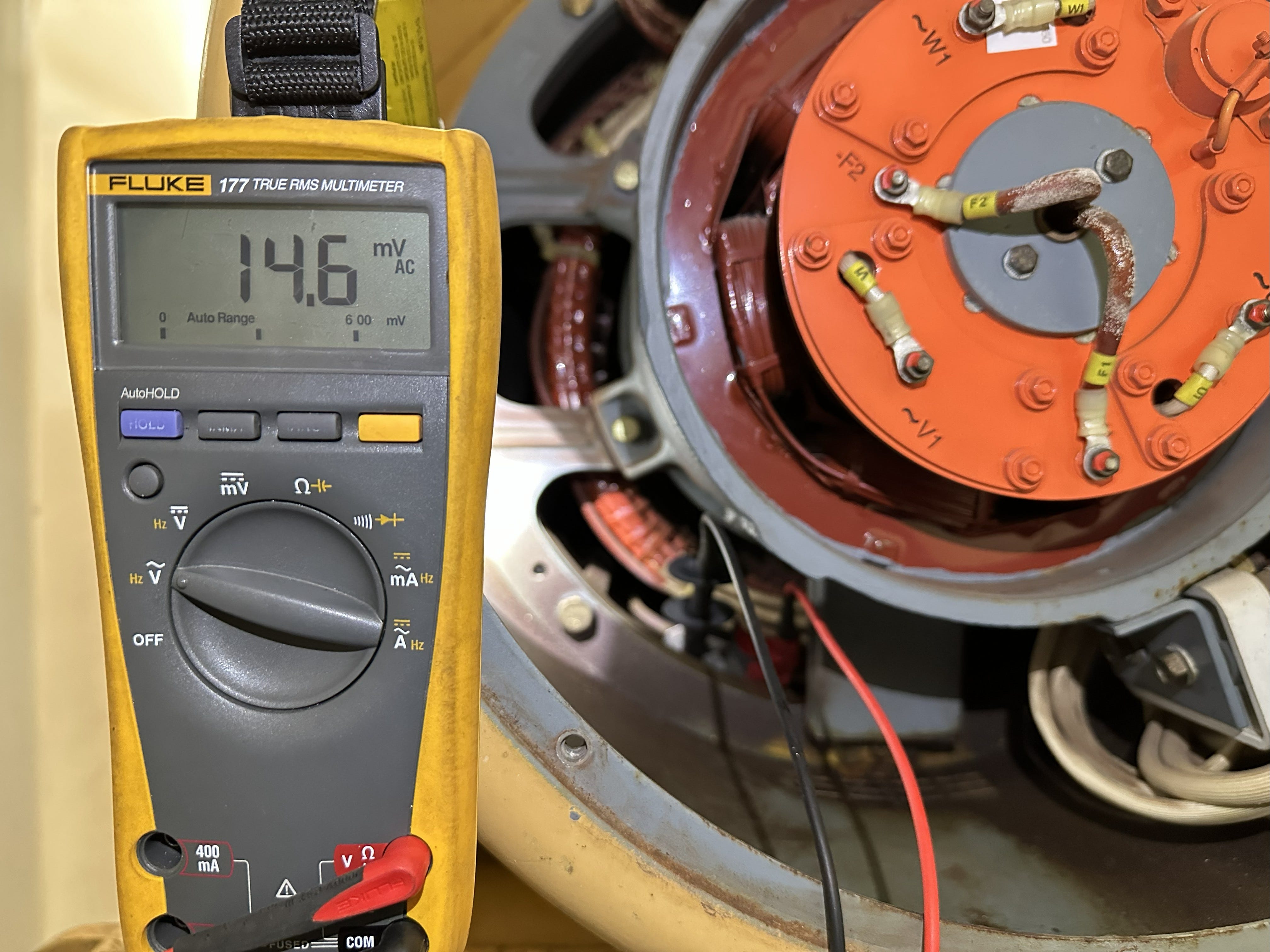
That’s essentially zero volts. By conventional logic, this circuit is dead. Safe to proceed with hands-on work.
But something—call it experience, intuition, or maybe just stubbornness—made me pause.
“Check line-to-ground first,” a voice in my head said. Probably the same voice that’s kept me alive this long.
I switched my probes and measured again.
Line 1 to Ground: 151.1V AC
Line 2 to Ground: 149.5V AC
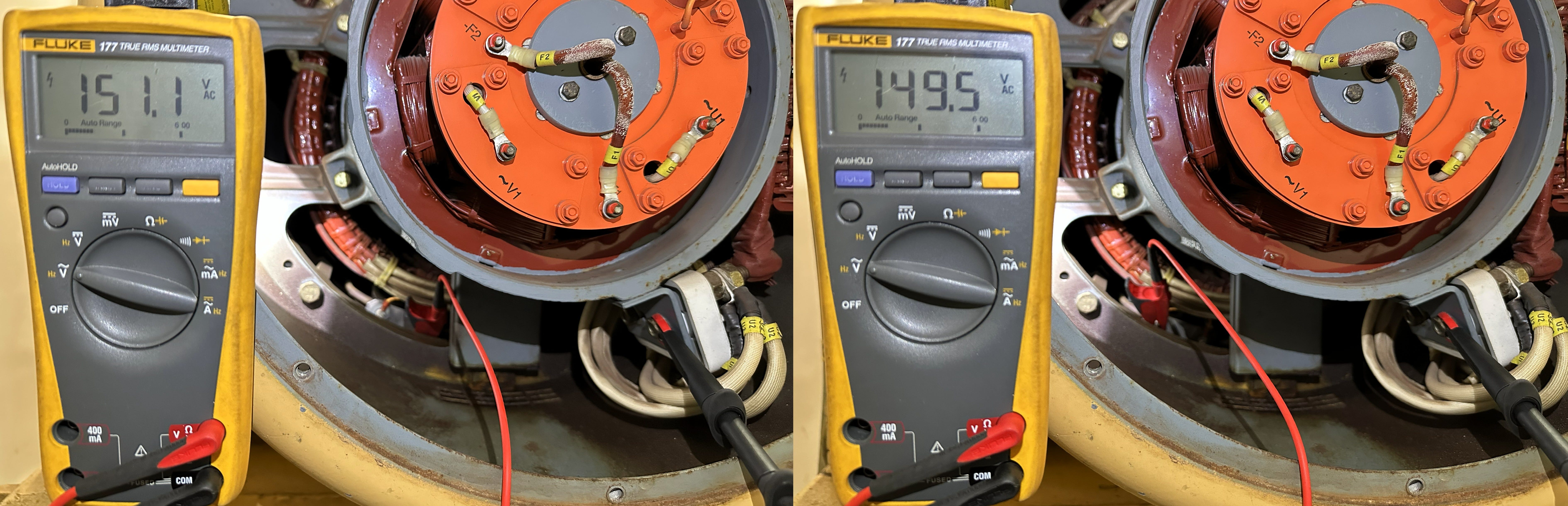
Both conductors were still energized at ~150V to ground.
Let that sink in for a moment.
The meter said “safe” line-to-line. But each wire was carrying enough voltage to seriously injure or kill me. If I had trusted that 14.6mV reading and touched either wire while grounded—standing on deck, leaning against the generator frame, holding a grounded tool—I would have completed a 150V circuit through my body.
At 150V through a human body (typically 1,000-10,000Ω resistance when wet or in contact with grounded metal), you’re looking at 15-150mA of current. The threshold for ventricular fibrillation—the kind of electrical shock that stops your heart—is around 100mA.
I was one assumption away from becoming a statistic.
Why This Happens More Often Than You Think
We’re all taught to “treat every circuit as live until proven otherwise.” But how do we prove it’s dead?
Most electricians check line-to-line voltage and call it good. The problem? Line-to-line voltage doesn’t tell you if a conductor is energized—it only tells you if there’s a potential difference between them.
Think about it like this:
Imagine two people standing on separate platforms, both 10 meters above the ground. The height difference between them is zero. But they’re both still 10 meters up. Fall off either platform, and you’re going to feel it.
That’s exactly what happened in my case.
The Measurements That Told the Story
Measurement Result What It Means
L1 - L2 14.6 mV AC Almost no potential difference
L1 - Ground 151.1 V AC Line 1 is live
L2 - Ground 149.5 V AC Line 2 is live
Both lines were energized at nearly the same potential relative to ground. They weren’t at opposing phases—they were effectively at the same phase, or one line had lost its proper reference and was floating at the potential of the other.
Why Line-to-Line Said “Almost Zero”
When both conductors sit at nearly identical potentials to ground (~150V each), the difference between them is minimal—only 1.6V in this case.
However, the multimeter displayed 14.6mV instead of the expected 1.6V. This discrepancy occurs due to:
Measurement noise in high-impedance fault conditions
Meter loading effects when measuring through resistive loads
Contact resistance in the measurement circuit
Electromagnetic interference in the switchboard environment
Your multimeter, measuring L-L, sees virtually no potential difference and reads near-zero volts.
But each conductor is still live at 150V to ground.
The Low-Resistance Load Factor
This case had an additional dangerous characteristic: the load was a low-resistance heating element (265.6Ω).
When a resistive load with low resistance connects two conductors that are at similar potentials, it creates a near-short path between them. In this fault condition:
Line 1 (the “live” wire) feeds through the low-resistance heater element
Current flows through the 265.6Ω load to Line 2
Both conductors equilibrate to nearly the same voltage relative to ground
The voltage across the load collapses (hence 14.6mV L-L)
But the voltage on each conductor to ground remains dangerously high
The heater wasn’t heating because there was insufficient voltage across it to drive meaningful current and generate heat. But touch either wire while grounded, and you complete a 150V circuit through your body.
The Forensic Investigation: Finding the Root Cause
This voltage signature pointed to a lost phase or open circuit condition upstream. Time to trace backwards.
Step 1: Check the Source
Started at the 230V supply source, working my way down:
Double-pole switch -S5:
Line side Terminal 1-4: 236.2V AC ✅ (good)
Load side Terminal 2-3: 236.2V AC ✅ (good)
Conclusion: Switch -S5 is functioning properly
Step 2: Check Downstream Components
Downstream of -S5 are the auxiliary contacts of contactor -K6:
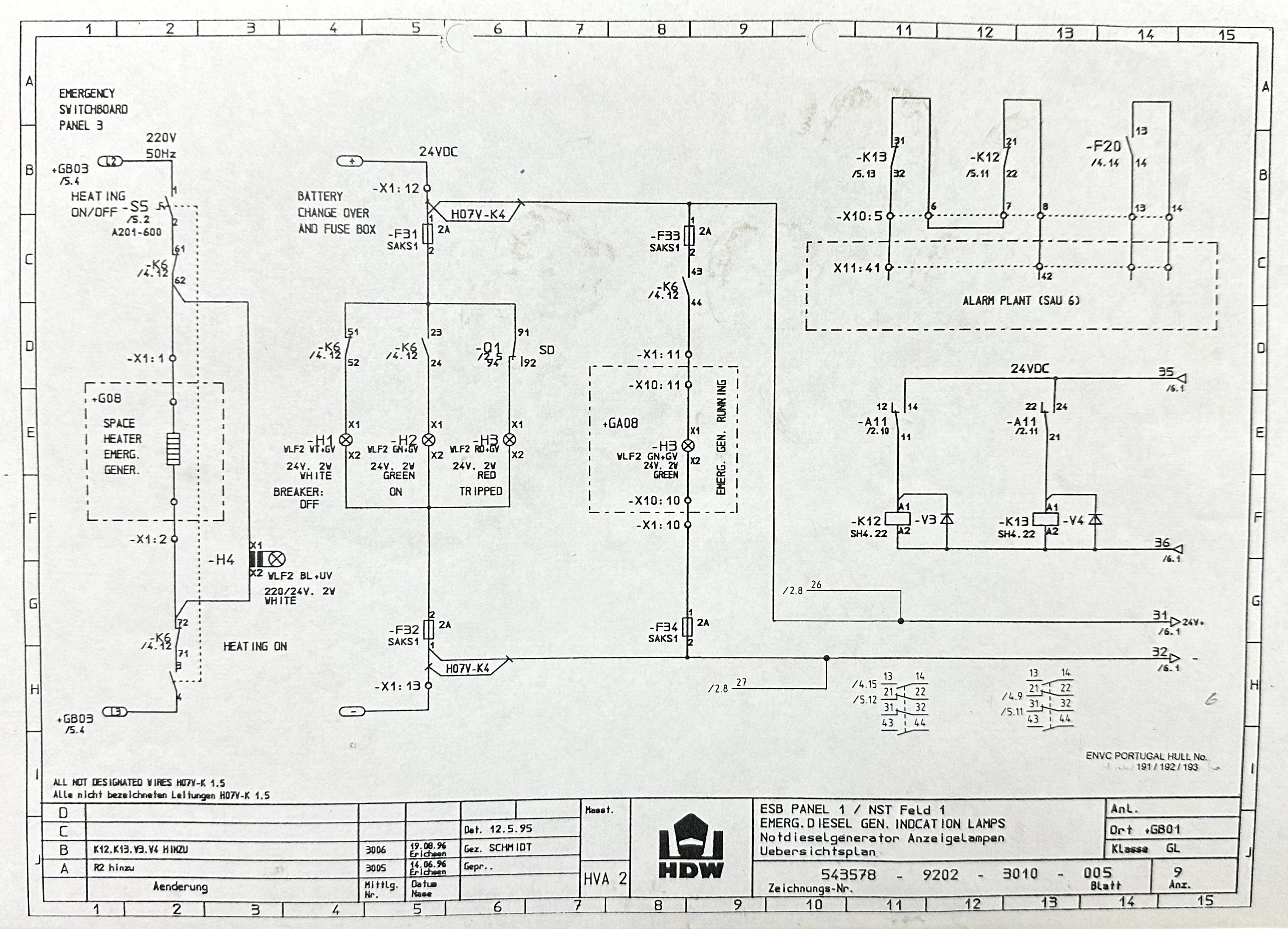
N.C. 61-62 (for Line 1): 45.3Ω (elevated but functional—indicates developing corrosion, acceptable for this application but warrants monitoring)
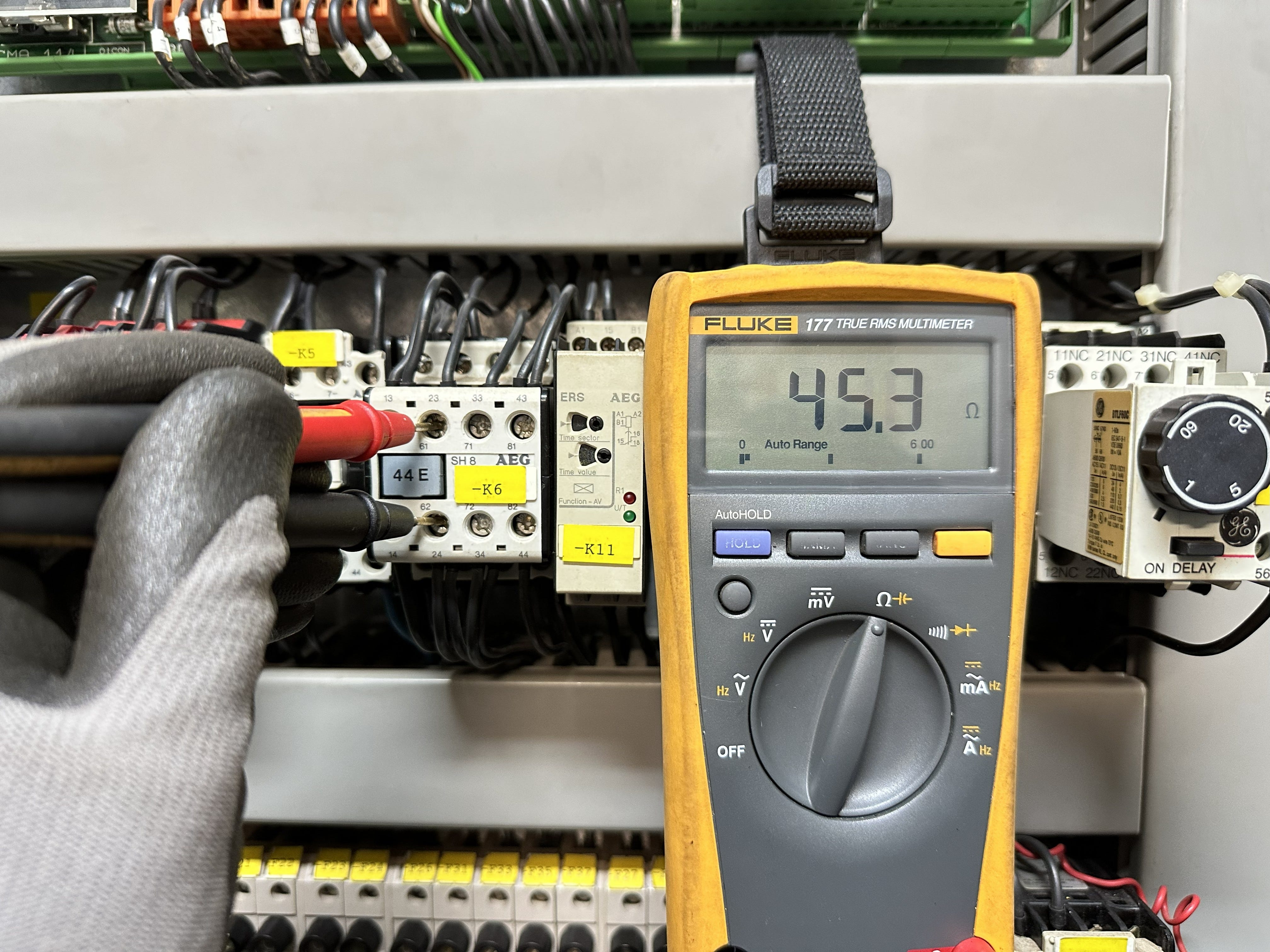
N.C. 71-72 (for Line 2): 11.81 MΩ ❌ OPEN CIRCUIT
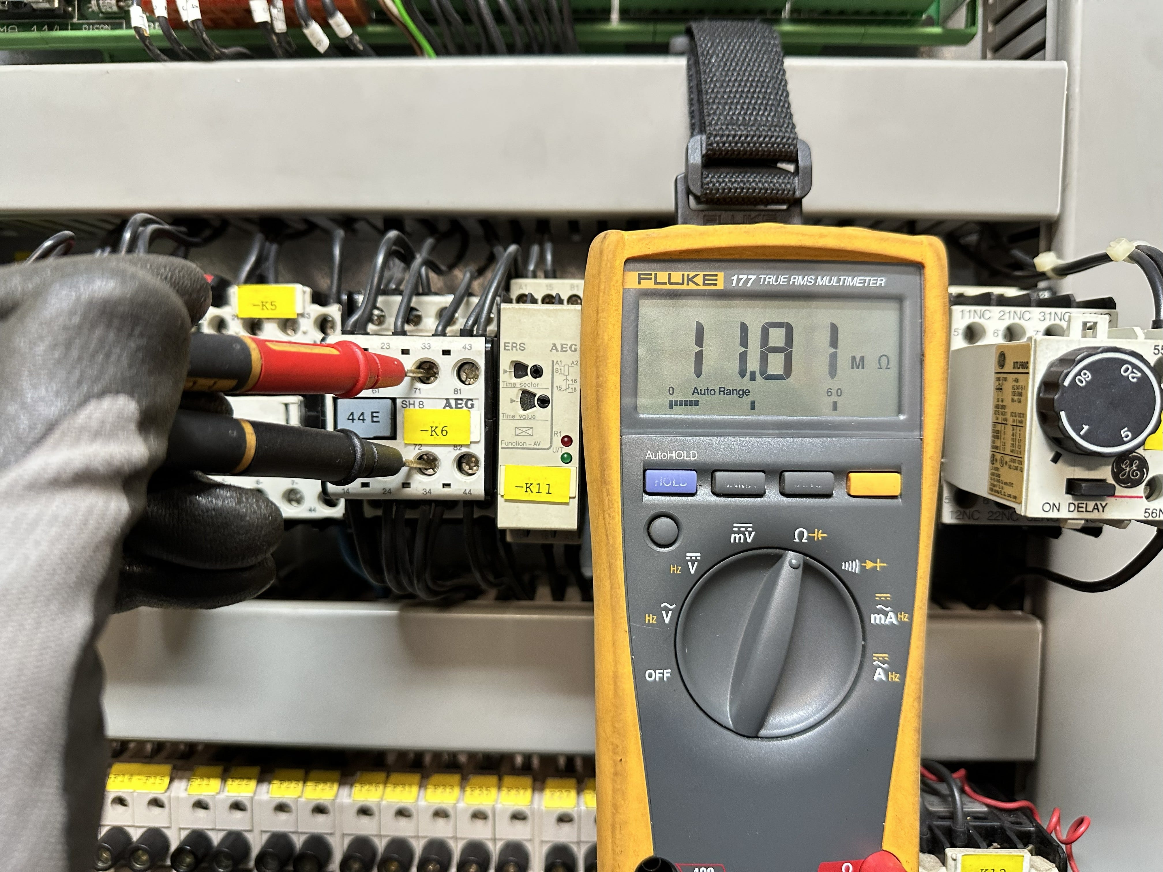
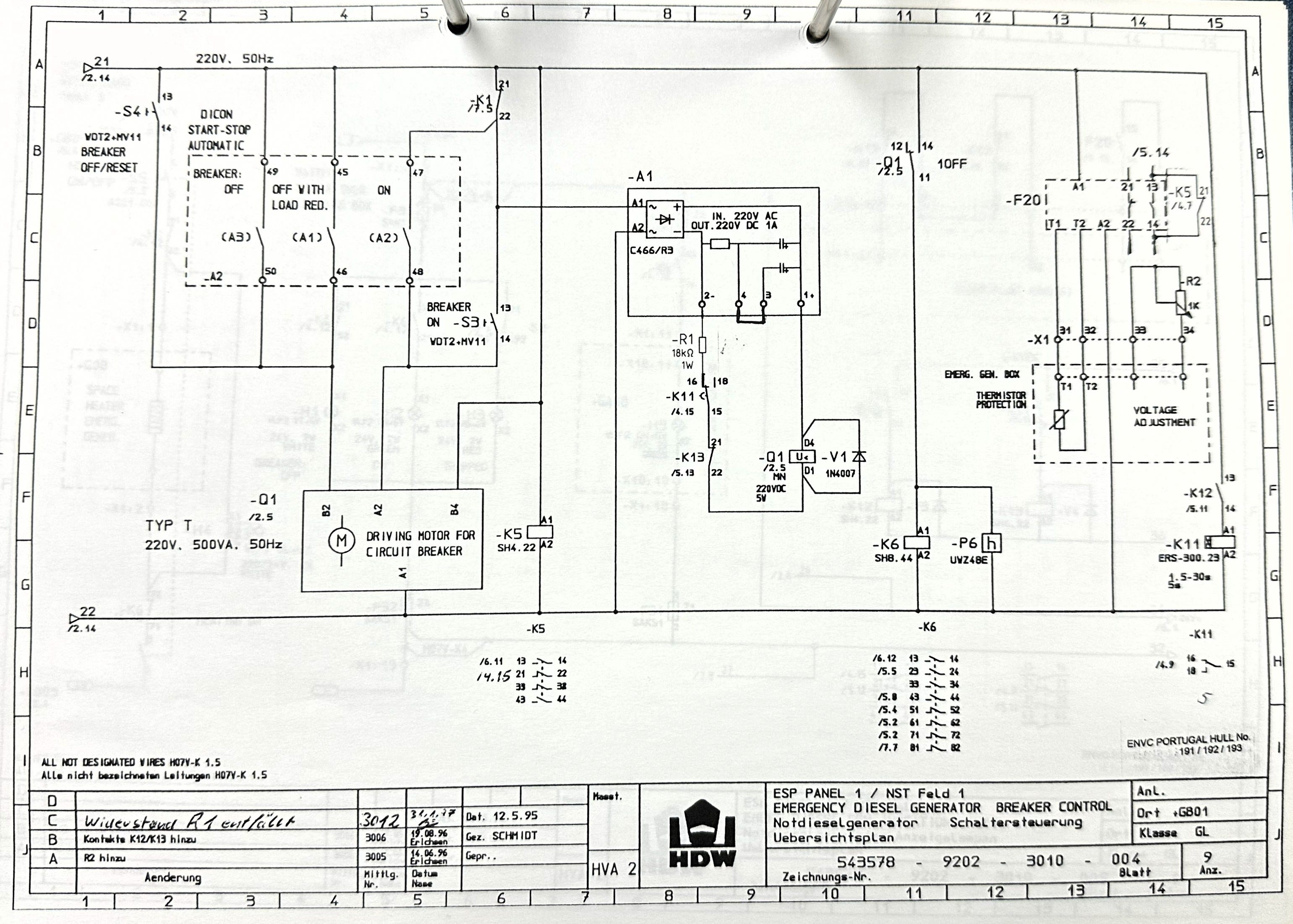
Context: Contactor -K6 energizes when the emergency generator is running. When the generator is stopped, -K6 is de-energized, and contacts 61-62 and 71-72 close to supply power to the space heater
.
What Was Actually Happening (The Physics)
With the bad contact at N.C. 71-72 creating an open loop:
Line 1 maintained its proper connection through contact 61-62
Line 2 lost its supply connection due to the open 71-72 contact
But Line 2 wasn’t completely isolated—it was connected to Line 1 through the 265.6Ω heater load
Voltage from Line 1 “fed through” the heater element to Line 2
Both conductors equilibrated to approximately the same potential (~150V to ground)
Voltage across the heater collapsed to near-zero (no potential difference = no heating)
Shock hazard remained on both conductors
This is a textbook floating phase condition caused by an open circuit in one supply line, with a low-resistance load providing the path for voltage to appear on the “dead” conductor.
The Fix: Immediate Action and Long-Term Solution
What I Did NOT Do:
❌ Touch the circuit
❌ Assume “close enough to zero” meant safe
❌ Proceed with maintenance based on the L-L reading alone
What I DID Do:
Immediate Action:
Did NOT proceed with maintenance despite the 14.6mV L-L reading
Switched off -S5 for space heater isolation
Verified de-energization using both L-L AND L-G measurements after isolation:
L1-L2: 0V ✅
L1-G: 0V ✅
L2-G: 0V ✅
Only then proceeded with safe hands-on work
Root Cause Investigation:
Traced supply wiring to Emergency Switchboard control panel
Identified failed auxiliary contact N.C. 71-72 on contactor -K6
Documented fault condition with photos and measurements
The Repair Challenge:
Immediate replacement of the contactor wasn’t feasible because:
The job requires a complete ESB blackout
One auxiliary contact is integrated into the bus tie breaker under-voltage trip circuit
Cannot safely perform this work during vessel operations
The Workaround:
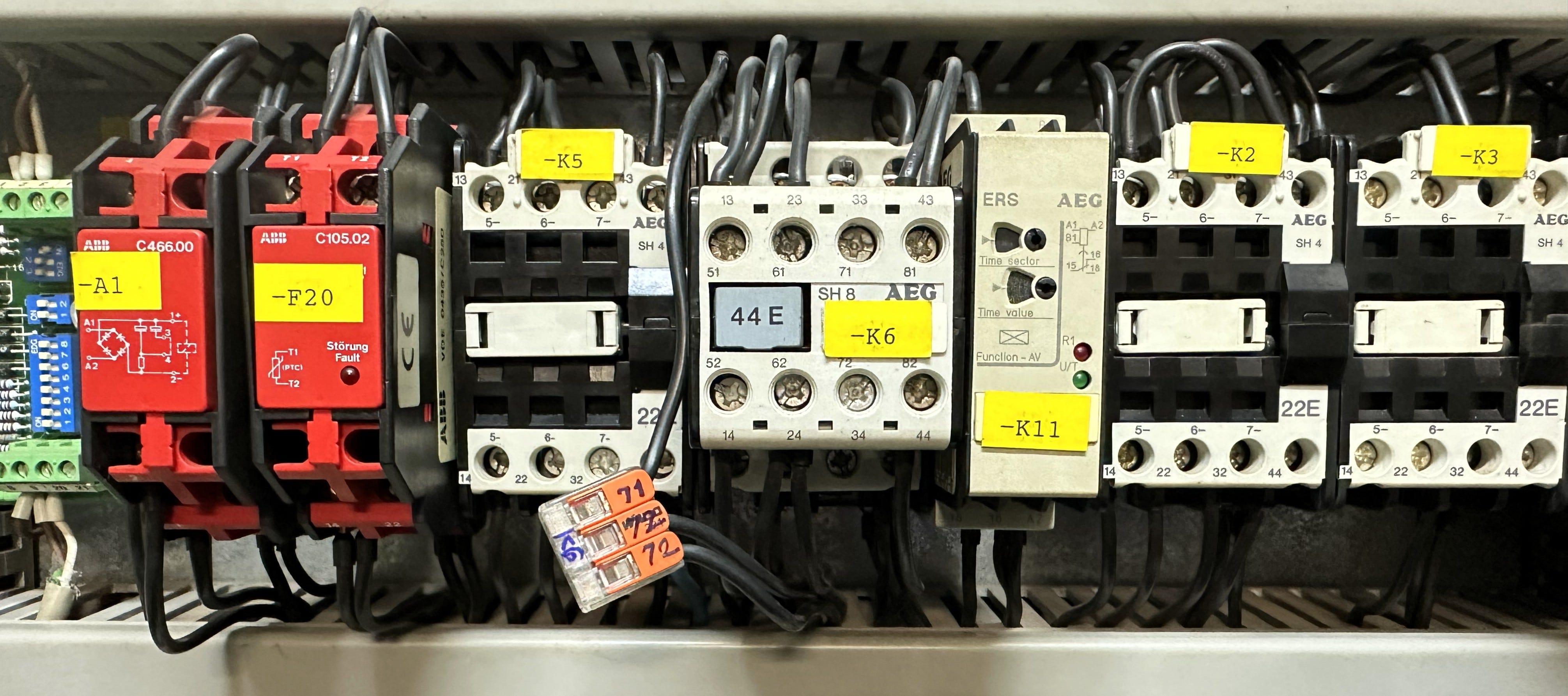
Caption: Temporary bypass using Wago connector with appropriate wire gauge until scheduled ESB blackout for full contactor replacement.
Implemented temporary bypass of failed 71-72 contact using Wago connector
Proper wire gauge selected to handle rated current
Restored automatic operation via single-pole switching through remaining functional contact 61-62
Full two-pole switching to be restored during next scheduled maintenance window at anchorage/berth
Safety Note: While single-pole switching is not ideal for a 230V circuit, it remains functionally safe in this application as the contactor provides definite break isolation when the generator is running.
Verification: Proving the Fix
After implementing the workaround, I measured again:
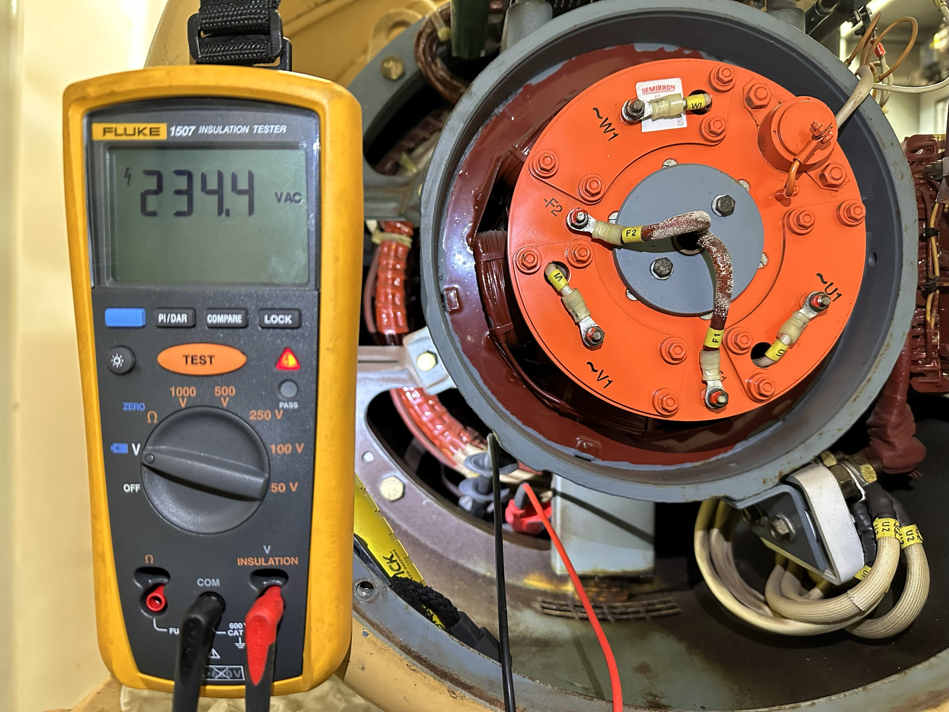
L1-L2: 234.4V AC ✅
L1-G: 154.1V AC ✅
L2-G: 121.1V AC ✅
Heater resistance: 265.6Ω (unchanged—heater element was always fine)
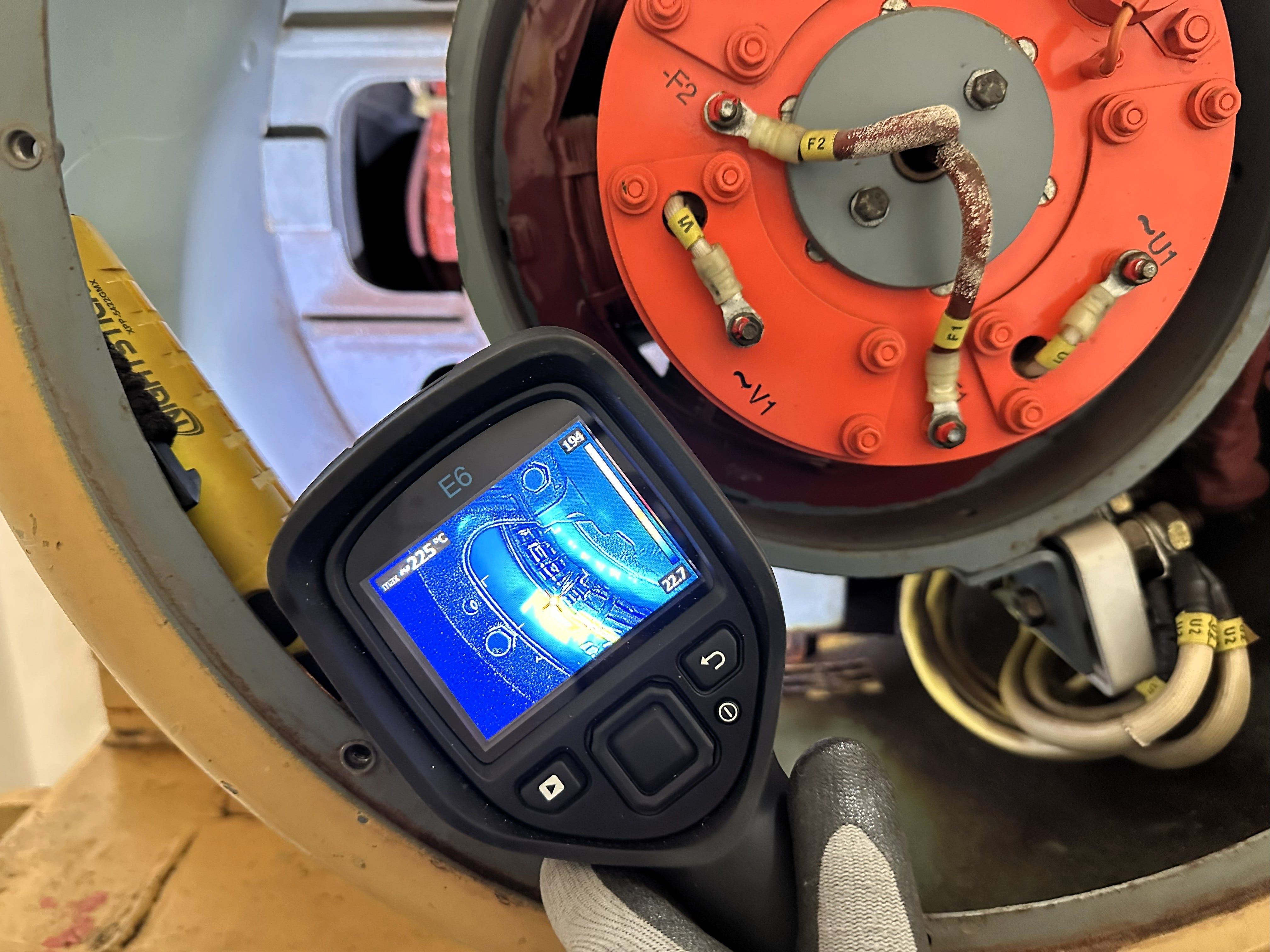
Heater operation: 225°C, heating normally ✅
Technical note: The L-G values (154.1V and 121.1V) don’t arithmetically sum to the L-L voltage (234.4V). This is normal for AC measurements where phase-to-ground voltages are referenced to a neutral/ground point, while phase-to-phase voltage represents the vector difference between phases. These values confirm proper phase balance and system integrity.
Space heater returned to full operation. Emergency generator winding protection restored.
Mission accomplished—safely.
The Bigger Lesson: It’s Not About the Meter
Here’s what this case really taught me:
The meter didn’t lie to me. It gave me exactly the information I asked for. The problem was that I almost didn’t ask the complete question.
Line-to-line voltage told me one truth: there was minimal potential difference between the two conductors.
But that’s only half the story.
Line-to-ground voltage told me the other truth: both conductors were dangerously energized relative to ground.
Both measurements were accurate. Both were necessary. One alone was dangerously incomplete.
This is the difference between troubleshooting and gambling with your life.
The Protocol That Saves Lives
Before any hands-on electrical work, I follow this protocol religiously:
⚠️ Pre-Contact Safety Verification:
✅ Measure L-L on all phases (tells you voltage across the load)
✅ Measure L-G on EVERY conductor (tells you if YOU’RE about to become the circuit)
✅ Measure Ground-to-Potential Earth (verifies ground integrity)
✅ Test your meter on a known live source first (proves your meter is working)
✅ If in doubt, lock it out (isolation is always safer than assumption)
This protocol has saved my life more times than I can count. It’ll save yours too.
Watch It In Action
Want to see this principle demonstrated in the field? I captured a similar scenario in Chapter 3 of my ProbeLem YouTube series, where I traced the Bridge Central Console (BCC) cooling fans circuit.
[Embedded YouTube video or link]
The measurements in that case:
Line 1 to ground: 119 volts ⚡
Line 2 to ground: 117 volts ⚡
Line-to-line: 0 volts
Same condition—both conductors energized, but line-to-line shows nothing. The video demonstrates why checking line-to-line alone gives you zero context, and why we must test all spectrums of the circuit to understand what’s really happening.
Your Turn: Share Your Close Call
I’d bet money that if you’ve worked with electrical systems for any length of time, you’ve had a similar near-miss. Maybe you caught it like I did. Maybe you learned the hard way.
Question for the community: Have you ever encountered a circuit that tested “dead” L-L but was still energized L-G? What happened? How close did you get?
Hit reply and tell me your story. I read every response, and with your permission, I might feature your case in a future newsletter (anonymized, of course).
We learn more from near-misses than we do from textbooks. Let’s build a library of lessons that keeps people alive.
Final Thoughts
Electricity doesn’t forgive assumptions.
A near-zero line-to-line reading doesn’t mean “safe”—it means you haven’t asked the full question yet.
Until you probe line-to-ground on every conductor, you don’t know if a wire is truly dead or just waiting to bite.
In this case, the difference between a 14.6mV L-L reading and a 150V L-G reading was the difference between safe maintenance and a potentially fatal shock.
Line-to-line tells you the voltage across the load.
Line-to-ground tells you if YOU’RE about to become part of the circuit.
Remember that the next time you’re standing in front of a panel, meter in hand.
Your life depends on asking the right questions.
Stay sharp. Stay grounded. Probe safely.
— ProbeLem
Resources & Next Steps
📚 Want the complete technical library? Full case studies, troubleshooting methodologies, and forensic breakdowns available on my Patreon: ProbeLem
🎥 Subscribe to ProbeLem on YouTube for field techniques, measurement demonstrations, and shipboard walkthroughs: ProbeLem
💬 Join the conversation on Facebook https://facebook.com/ProbeLemSolving where I share insights from the field
📧 Forward this newsletter to an ETO, marine electrician, or engineer who needs to see this
P.S. If this newsletter saved you from making a dangerous assumption, or if you know someone who needs to read this, please share it. One forwarded email could prevent a fatal accident.
This newsletter is written from the engine room, the switchboard, and the field—where real troubleshooting happens and real lives are on the line. Every case study is based on actual events. Names and vessel details are anonymized for privacy and security.
© 2025 ProbeLem. All technical content may be shared for educational purposes with attribution.

Comments
Post a Comment