Building a Makeshift Navtex Printer PSU Out of Spare Parts
ProbeBack | This entry is from my electrical job journal, before ProbeLem existed. March to May 2021. I documented this the way an ETO documents things... for the job record, not for an audience. Publishing it now as part of the ProbeLem Library.
The Handover
20 March 2021. I embarked the vessel and relieved my ETO batchmate from Norwegian Training Center Manila 2016. Good guy. Same batch, different contracts for years. This time we crossed paths at the gangway.
He handed over a few pending jobs... the usual stack when spares are still in transit. One item stood out:
Please install Power supply for Navtex Printer when the equipment arrives.

The new printer had arrived. The PSU had not.
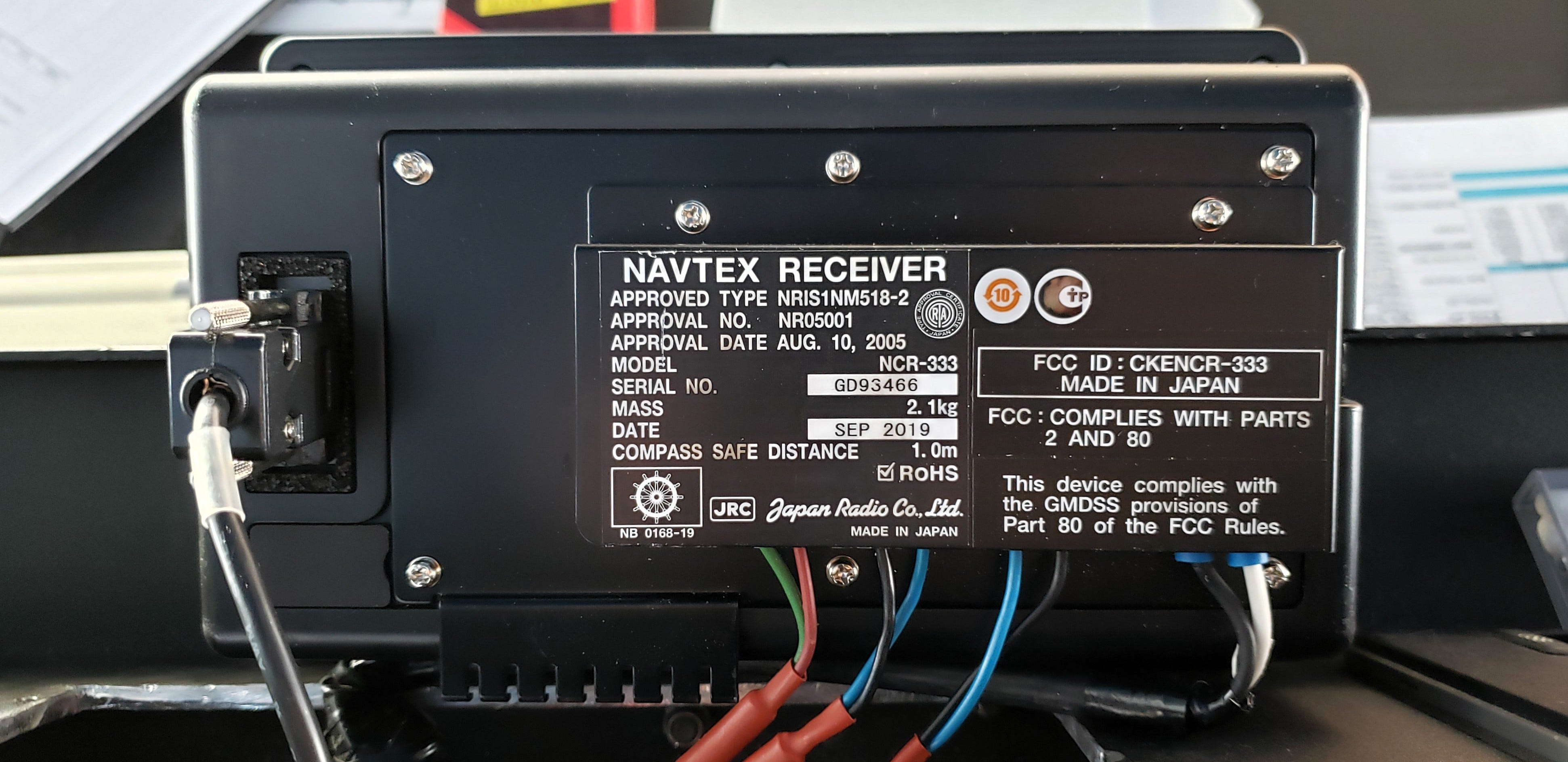
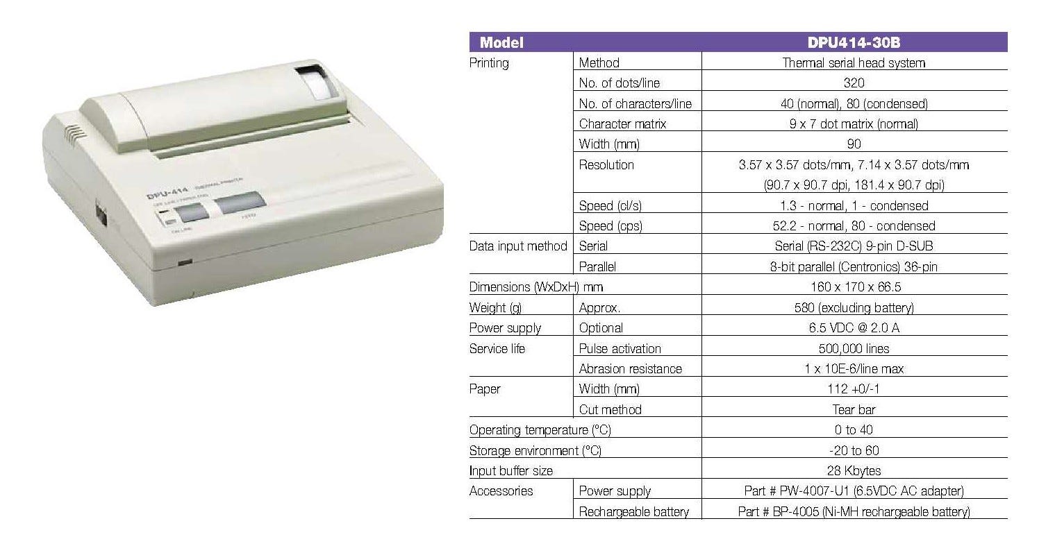
The Problem: There Is No Standard 7V Onboard
The DPU-414 datasheet was clear. The PSU was an optional accessory... a separate line item. Nobody flagged it during procurement. So now we had a brand-new portable printer on the bridge with no power.
I checked what was available in the spares store. Standard transformer secondaries onboard follow a predictable set: 12V, 24V, 48V. That is the world we live in at sea. There is no 7V transformer in a marine spare parts catalogue. It is a non-standard value.
That is where most people would stop... raise a defect report, wait weeks for the OEM spare to arrive. I had a different plan.
First, A Detour That Became the Key
Fast forward to May 2021. A batch of spare bridge rectifiers arrived onboard... GBPC5006 units, 600V/50A rated. Five pieces. My primary job for those rectifiers was to repair the PAGA Amplifier System B, No. 2.
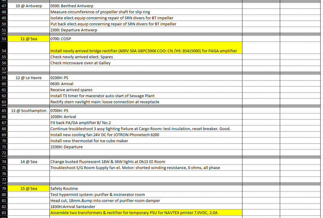
The amplifier had a failed bridge rectifier. That component converts the AC supply voltage into the DC rail that powers the amplifier circuitry. Dead bridge rectifier equals no DC rail equals non-functional PAGA System B. Since this is a redundant system with System A, operations were not disrupted... but a defect is a defect.
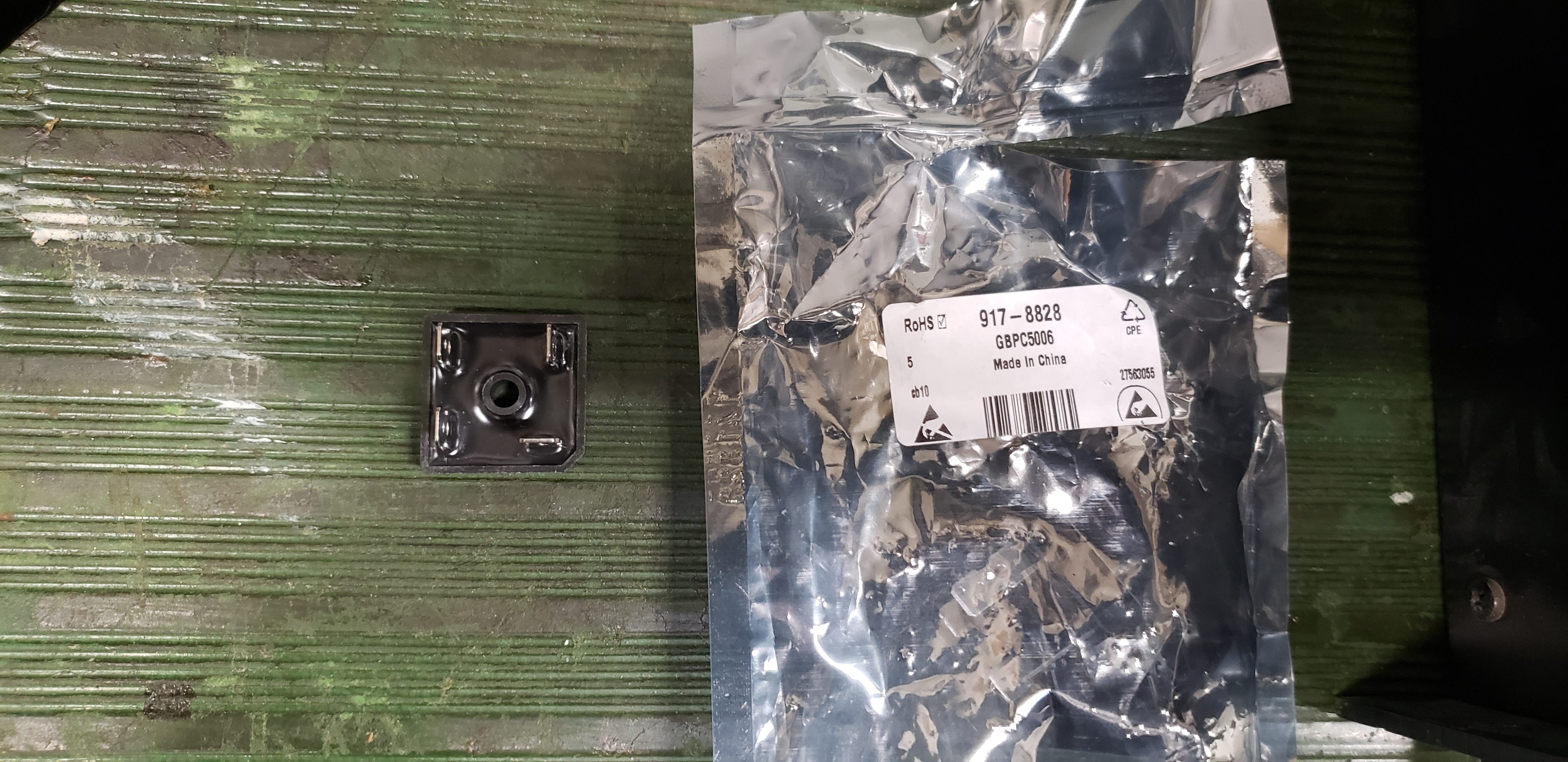
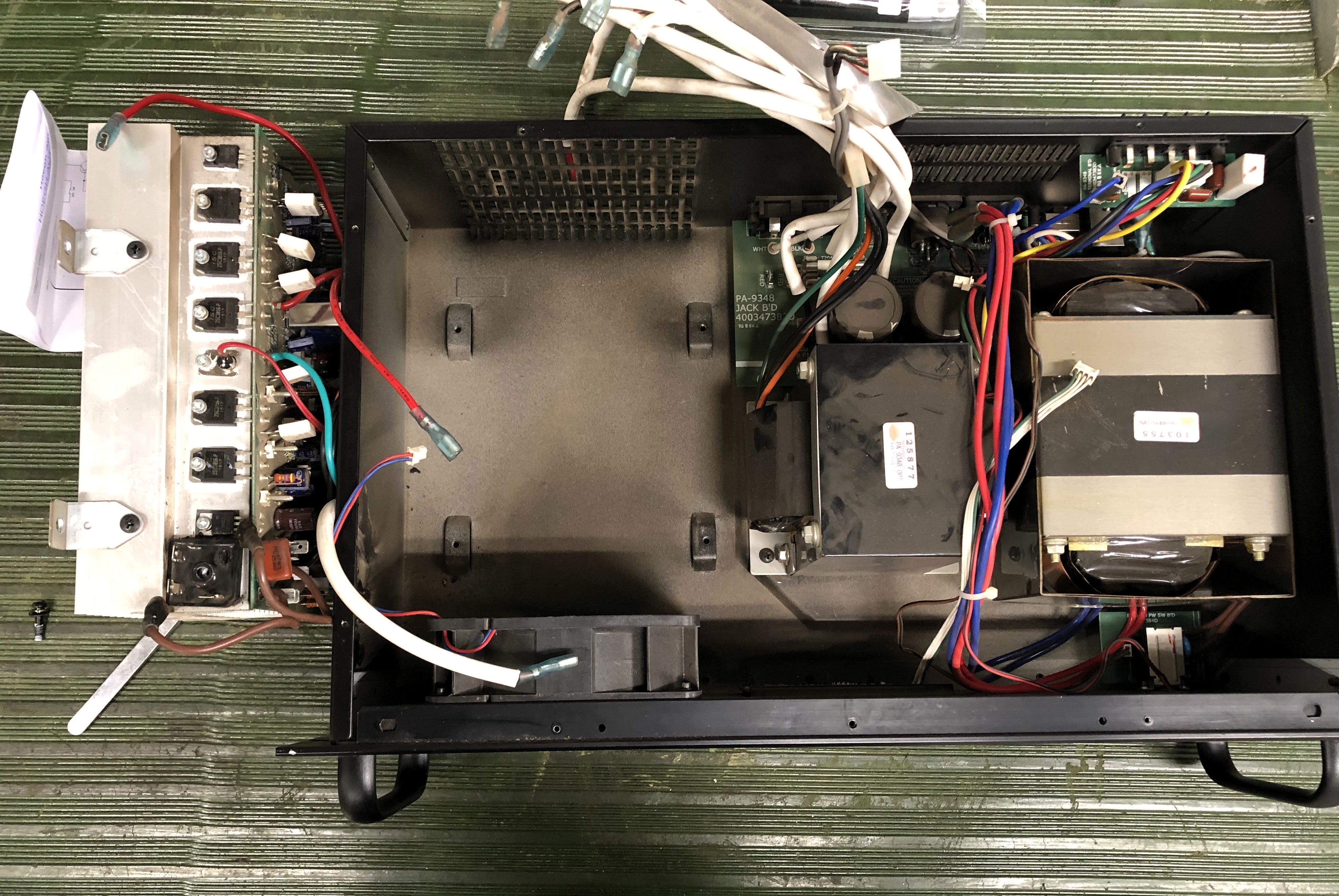
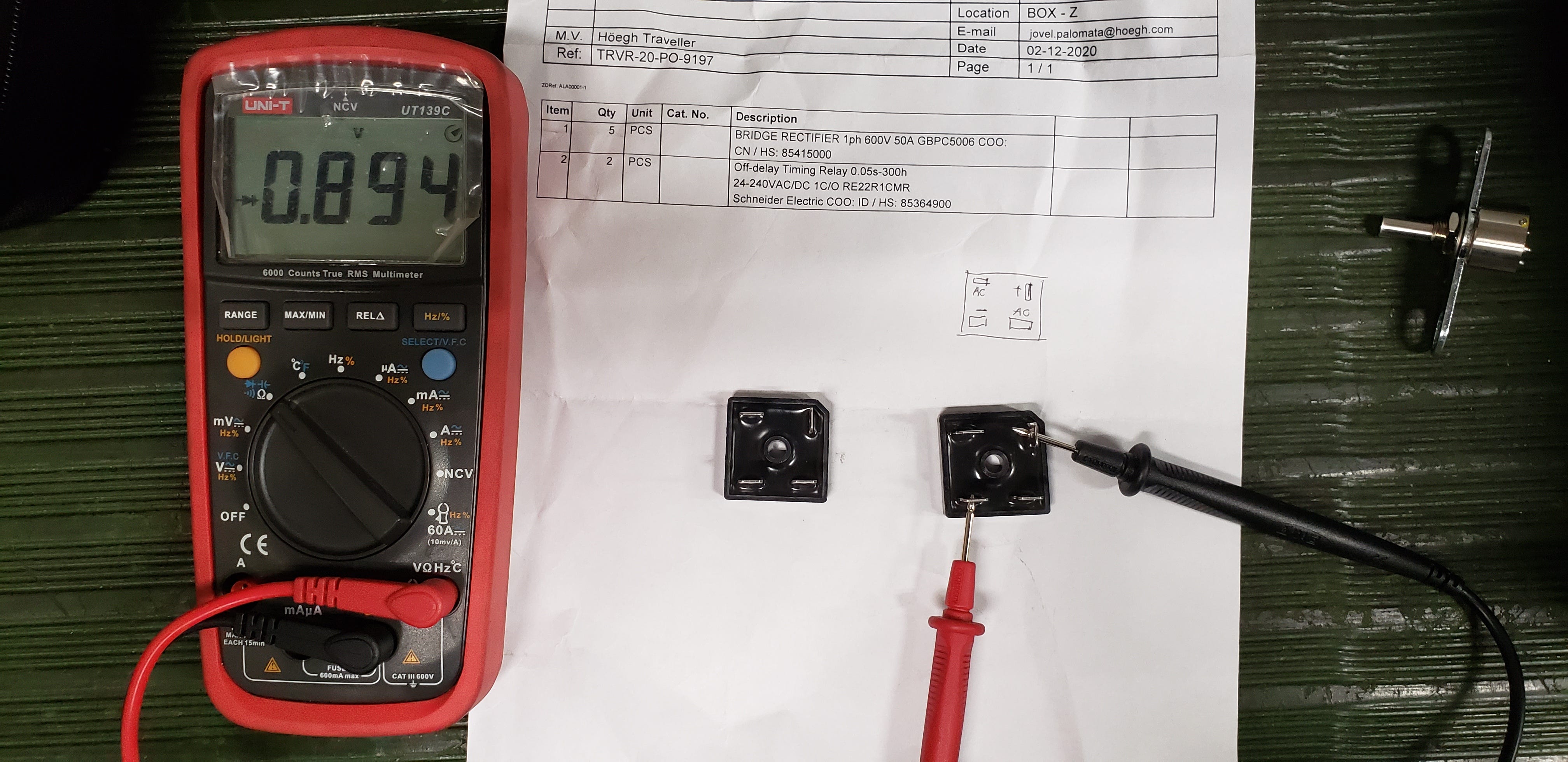
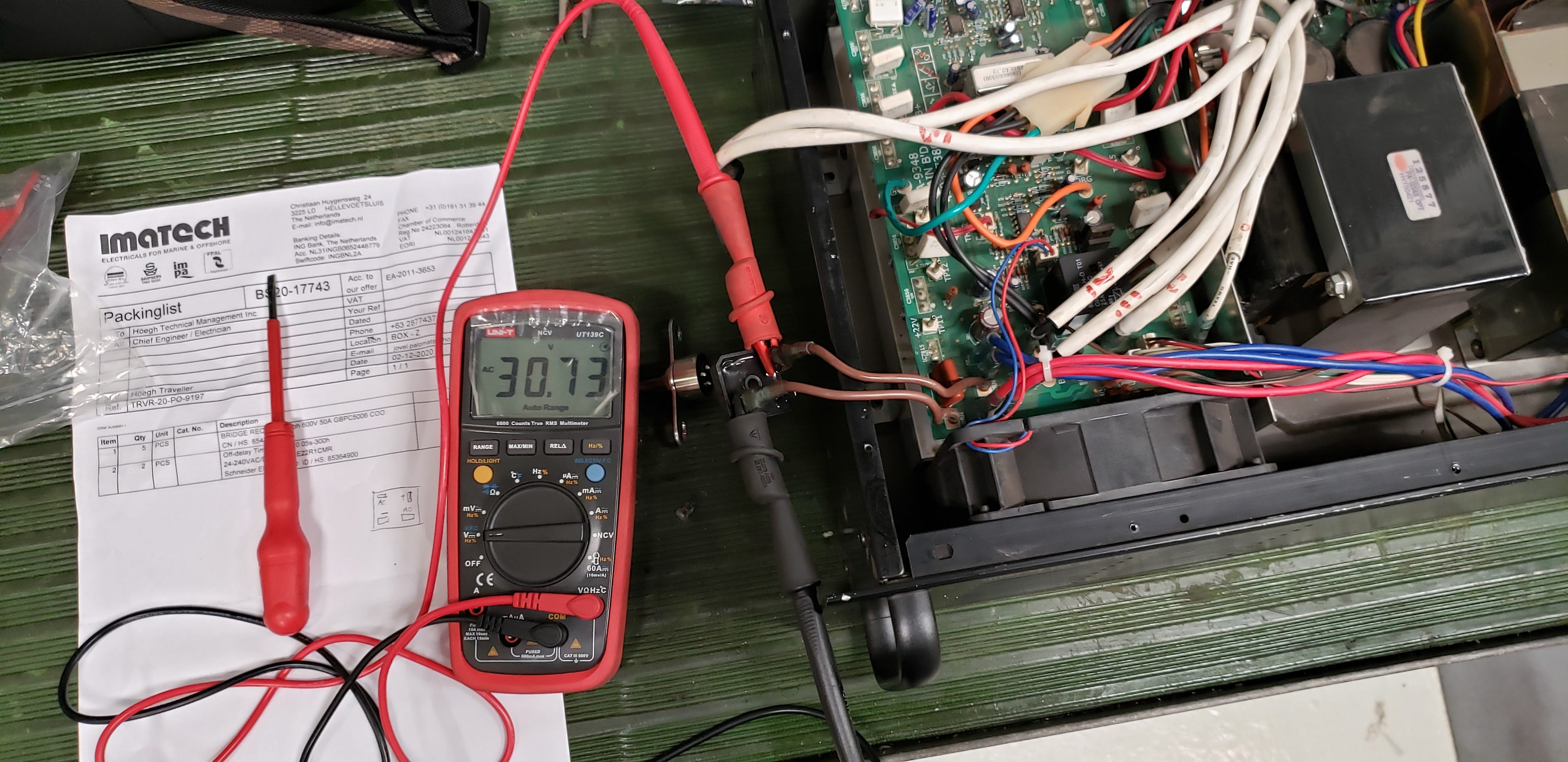
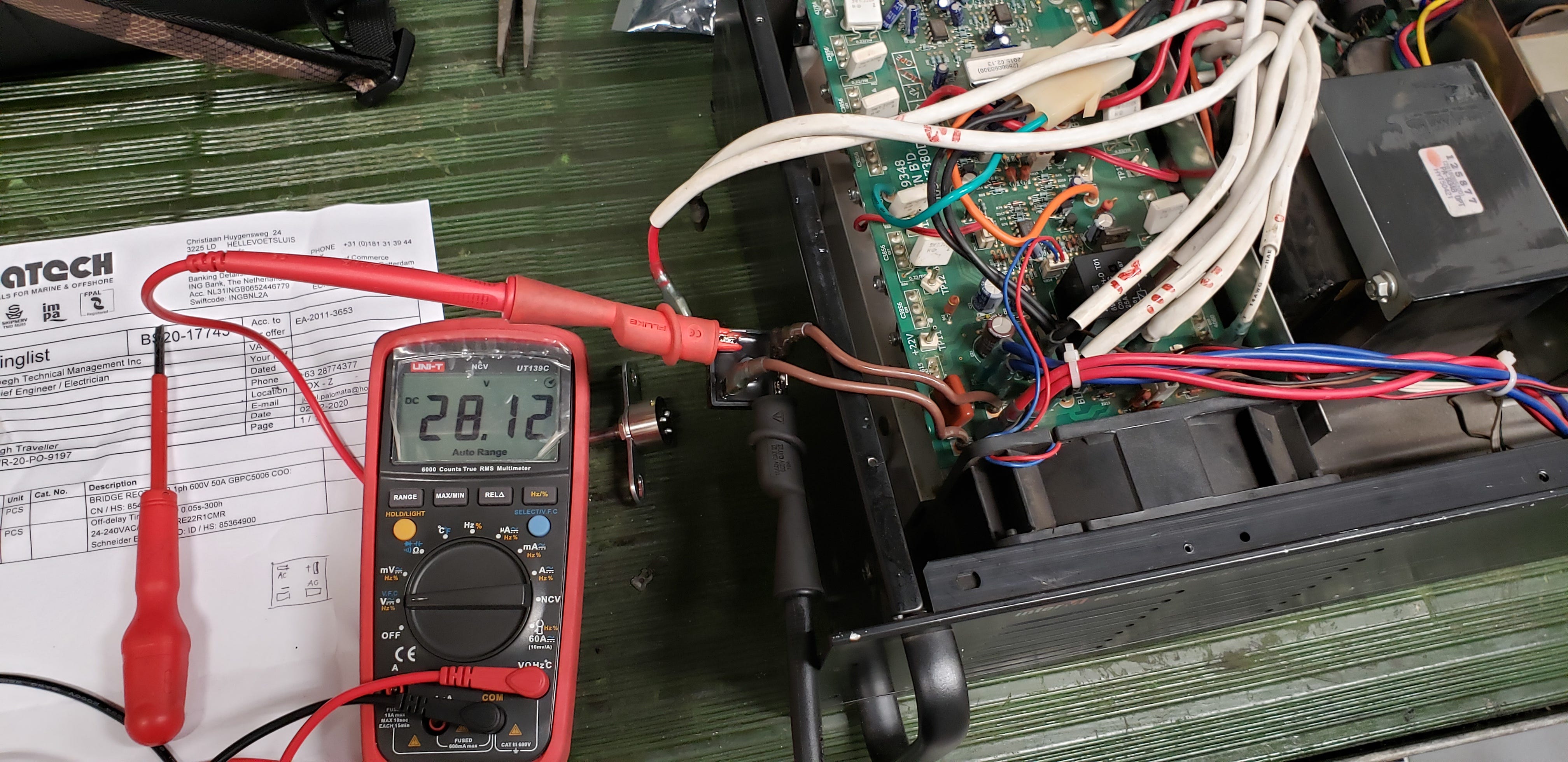
The amplifier was back online. System B, No. 2 restored to full redundant operation.
PAGA repair done. System B, No. 2 back online. And I had four bridge rectifiers left.
The solution is in the problem itself... and sometimes, it arrives as a spare for a different job.
The Math: Cascading Transformers to Find 7V
Since a standard 7V AC transformer did not exist in my spares, I had to construct that voltage by cascading two transformers. The principle: use the secondary output of Transformer 1 as the input to Transformer 2, and work backwards from the desired output voltage.
Here is the computation.
Transformer Ratio Formula
Turns ratio: n = Np / Ns = Vp / Vs
Where: Np = primary turns | Ns = secondary turns
Vp = primary voltage | Vs = secondary voltage
For two cascaded transformers (T1 output feeds T2 input):
Vs_final = V_input x (Vs_T1 / Vp_T1) x (Vs_T2 / Vp_T2)
Trial 1
Input voltage: 220V AC
Transformer 1:
Primary tap: 415V
Secondary tap: 230V
Ratio (n1): 415 / 230 = 1.804
T1 output: 220 / 1.804 = 121.95V AC
Transformer 2:
Primary tap: 440V
Secondary tap: 24V
Ratio (n2): 440 / 24 = 18.33
T2 output: 121.95 / 18.33 = 6.65V AC (theoretical)
Measured output: 7.69V A
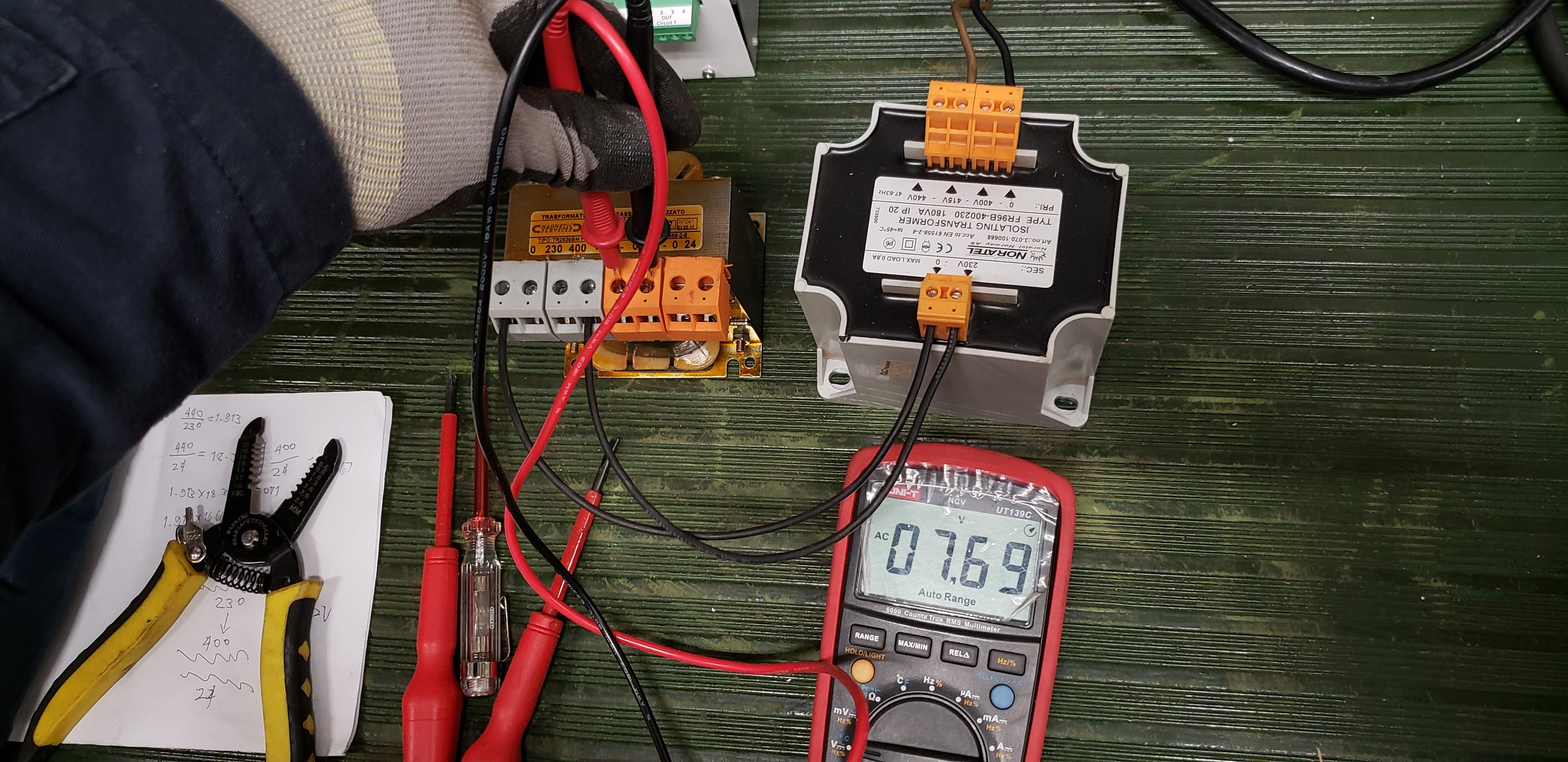
Note: Measured higher than theoretical because applying 220V to a 415V-rated primary tap means partial flux utilization. Actual secondary output is proportionally higher than the tap ratio alone would suggest.
Trial 2
Input voltage: 220V AC
Transformer 1:
Primary tap: 440V
Secondary tap: 230V
Ratio (n1): 440 / 230 = 1.913
T1 output: 220 / 1.913 = 115.0V AC
Transformer 2:
Primary tap: 440V
Secondary tap: 24V
Ratio (n2): 440 / 24 = 18.33
T2 output: 115.0 / 18.33 = 6.27V AC (theoretical)
Measured output: 7.22V AC
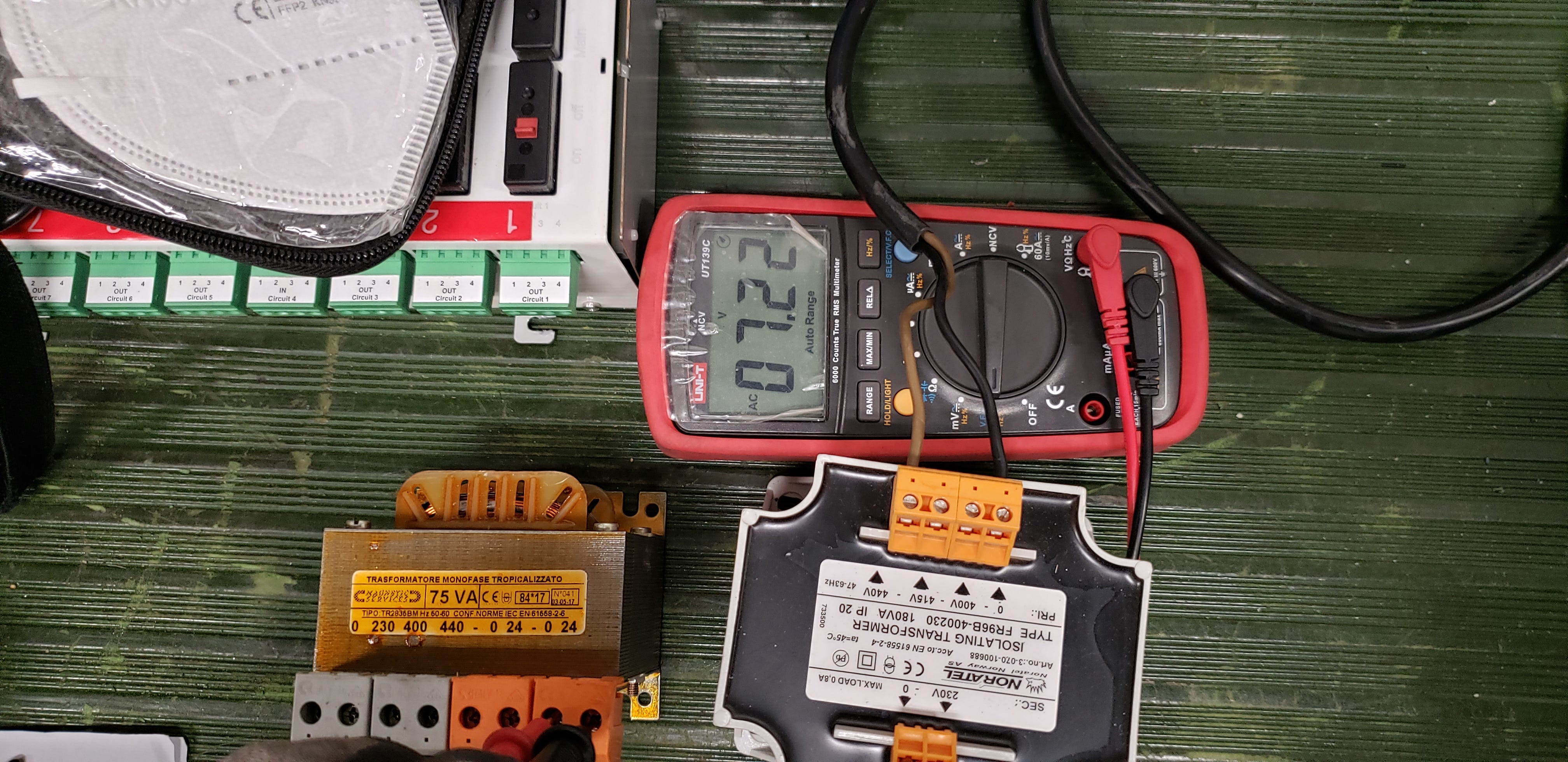
Note: Closer to theoretical. T1 now uses the 440V primary tap with 220V input, giving a more predictable step-down. Trial 2 became the working baseline.
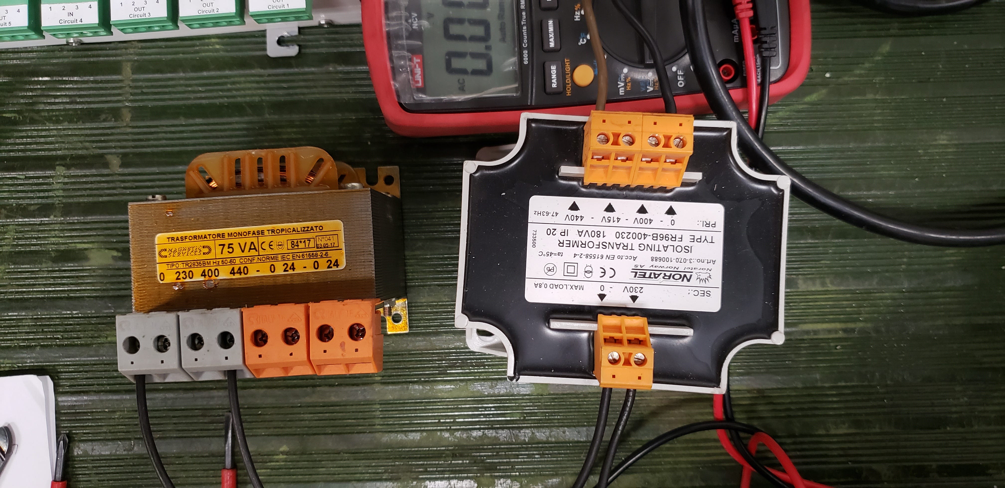
From AC to DC: Building the Makeshift PSU
Trial 2 gave me the working AC baseline at 7.22V. Now I needed to convert that to clean DC and tune it into the operating range of the DPU-414 printer.
Step 1: Rectification
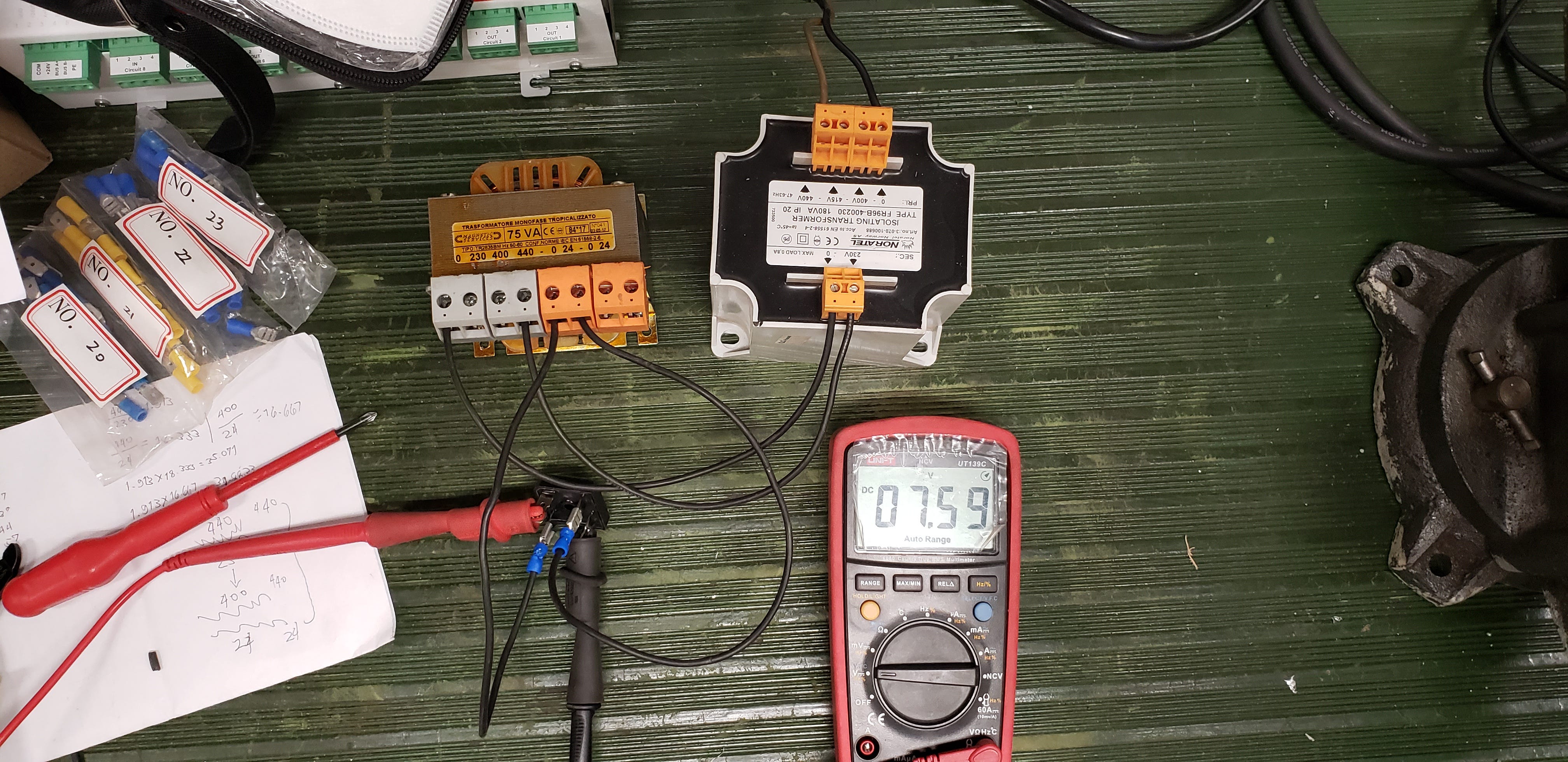
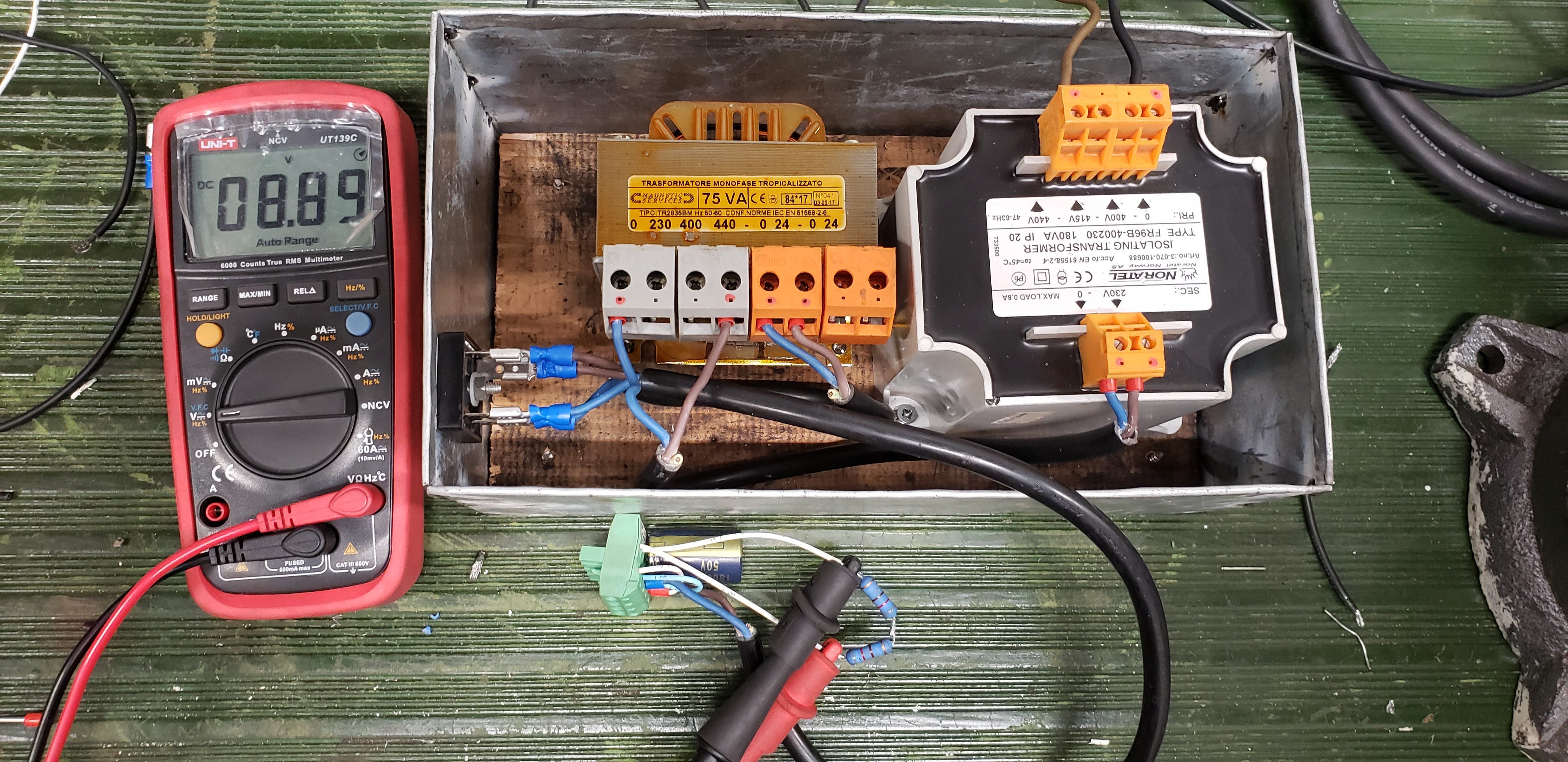
I connected one of the spare GBPC5006 bridge rectifiers across the Trial 2 output. A bridge rectifier converts alternating current to pulsating direct current by steering current through rectifier diode arranged in a bridge configuration. Full-wave rectification... both halves of the AC cycle contribute to the DC output.
The theoretical no-load DC output from a bridge rectifier is approximately:
Vdc (no-load) = Vac x 1.414 - Vf_total
Vdc (no-load) = 7.22 x 1.414 - 1.4 = 10.21 - 1.4 = ~8.81V DC (theoretical)
Measured: 7.59V DC
Note: Lower than theoretical due to transformer regulation under the capacitive load of measurement. Practical result.
Step 2: Ripple Filtering
Raw rectified DC rides on a ripple waveform. Not suitable for electronics. An electrolytic capacitor placed across the output smooths the ripple by charging during voltage peaks and discharging during troughs.
Two capacitor values tested:
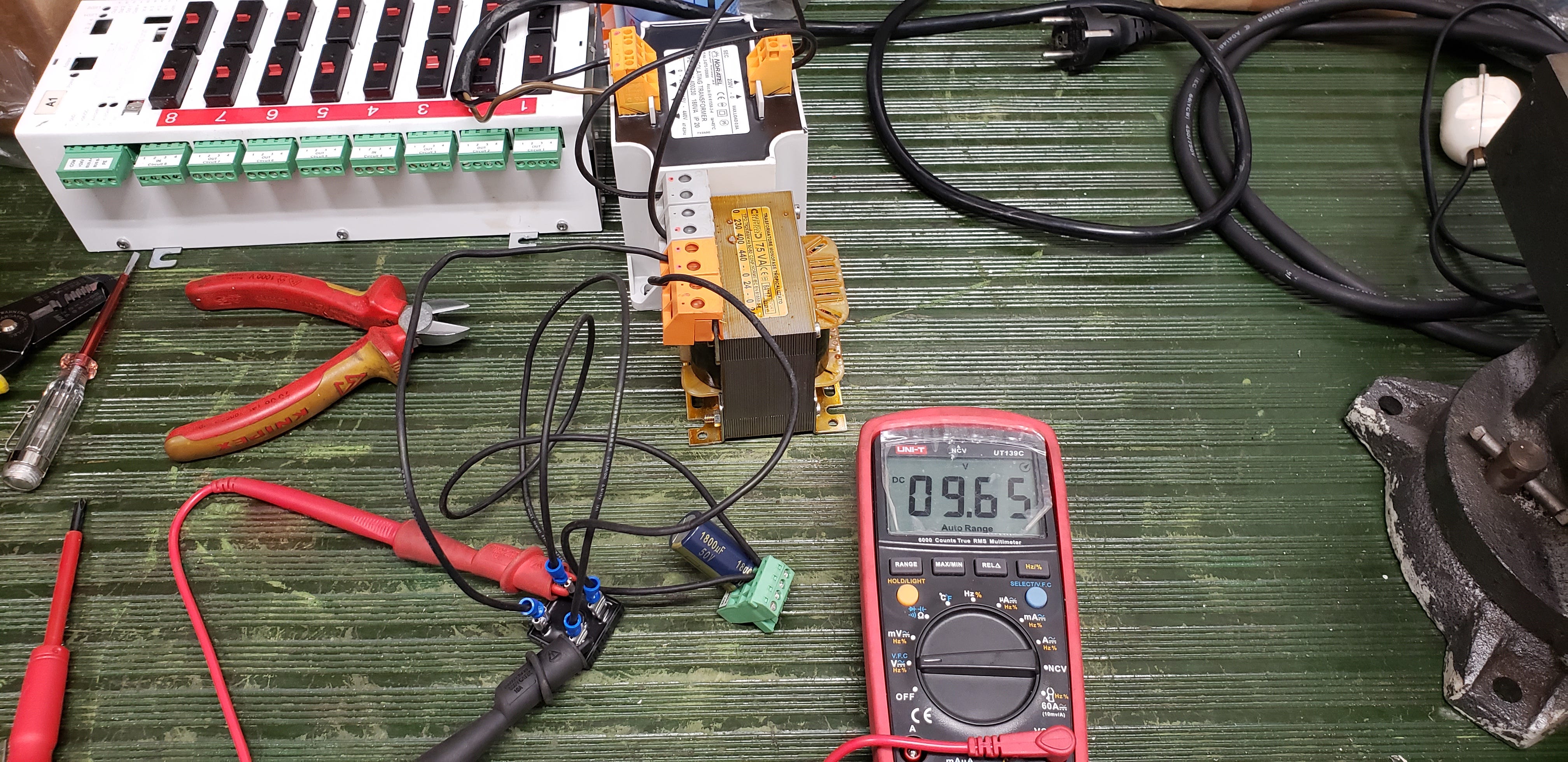
- 1800 microFarad, 50V rated: Output 9.65V DC. Excellent ripple suppression.
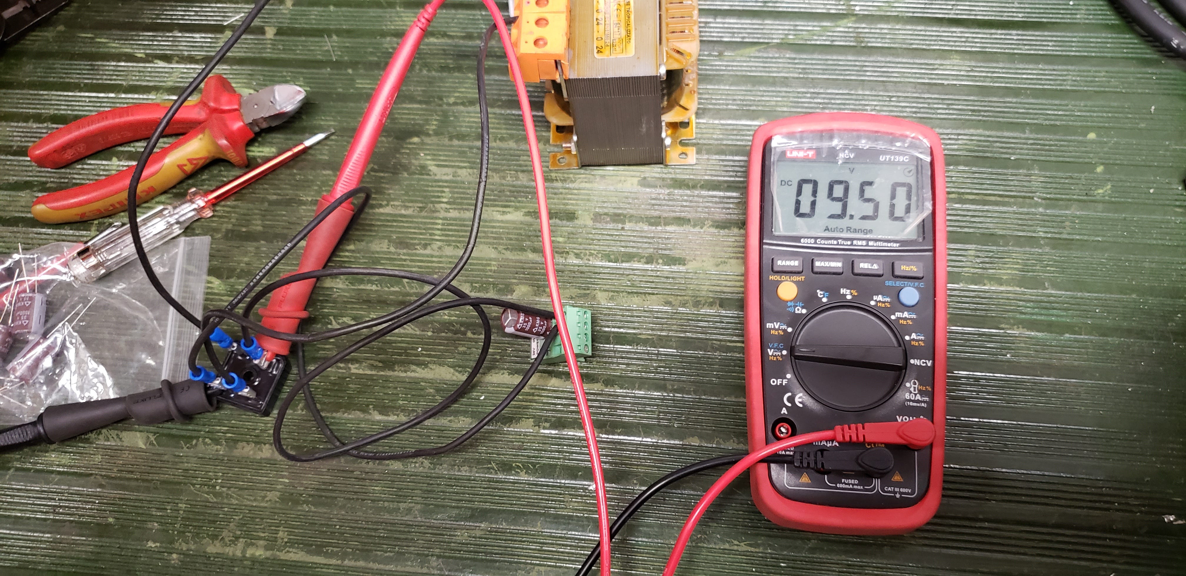
- 1000 microFarad, 35V rated: Output 9.50V DC. Slightly lower peak storage.
Step 3: Voltage Tuning with Bleed Resistors
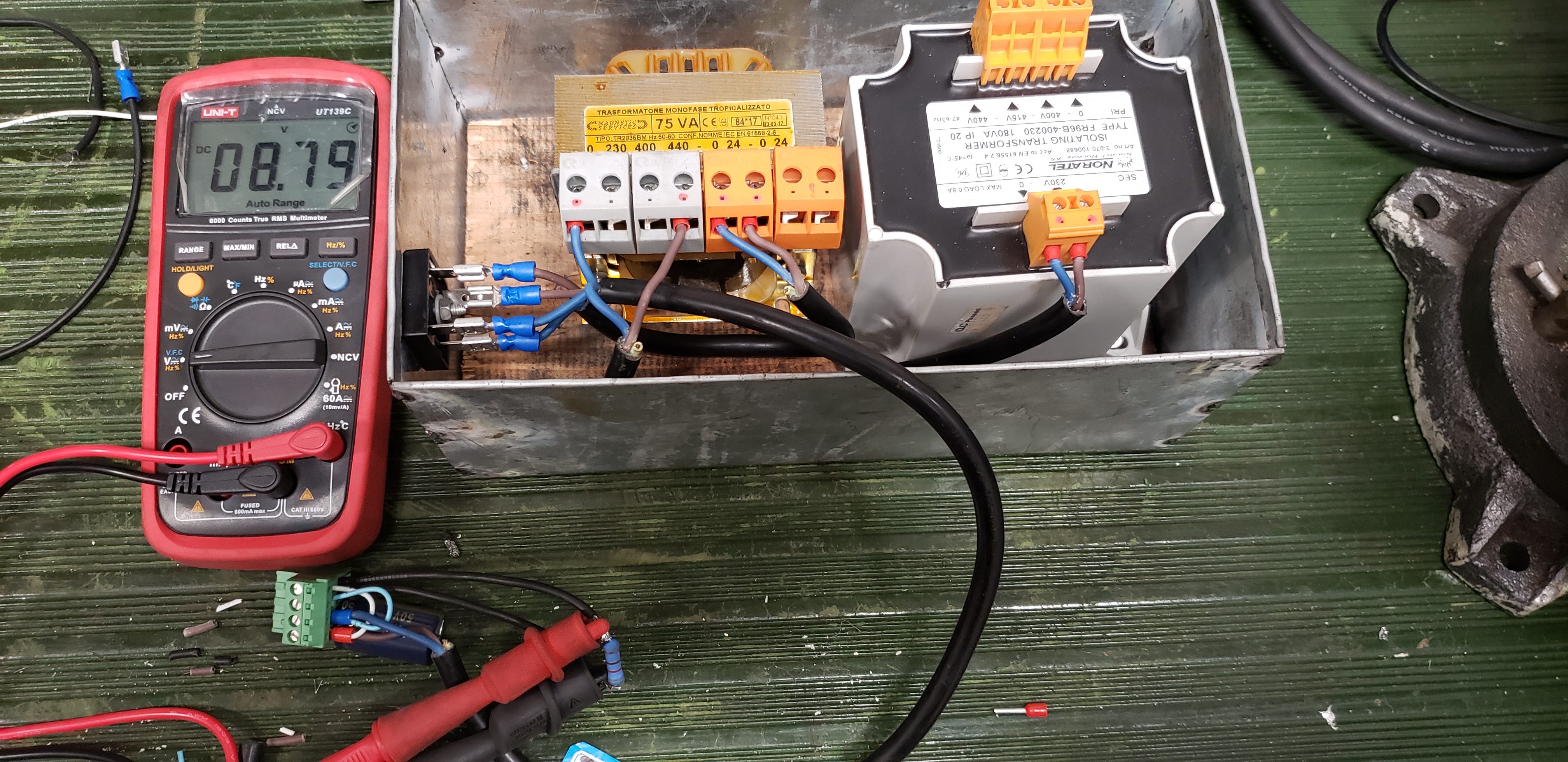
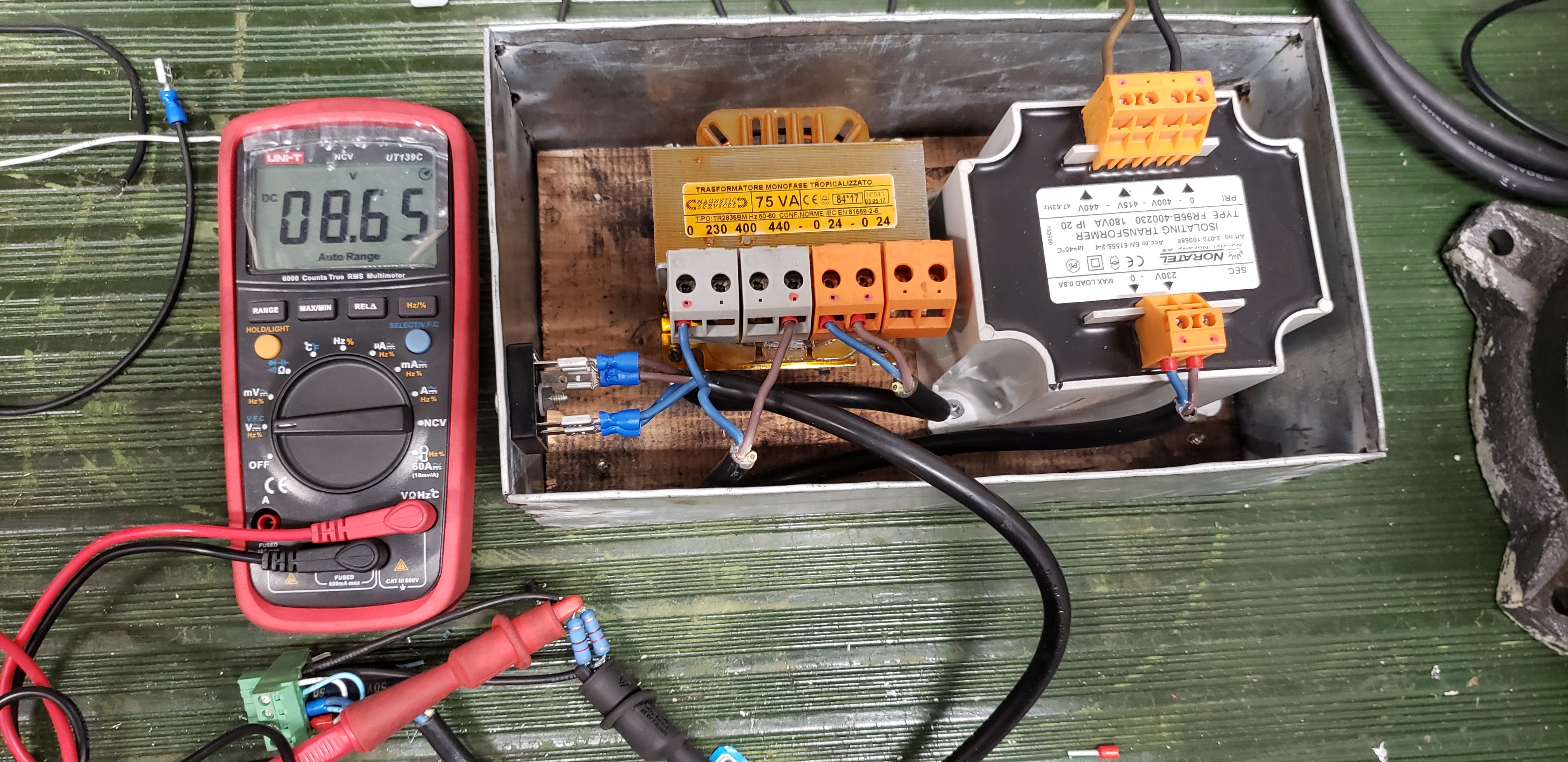
The no-load voltage was running above the 7V operating range. This is normal for an unregulated supply... the voltage settles once a real load is connected and drawing current. But to give the circuit a predictable working margin, I added resistors in series to create a deliberate voltage drop.
Based on the color bands visible in the bench photos, the resistors appear to be Brown-Black-Red, Gold... consistent with 1 kilo-ohm, 5% tolerance. The voltage drop observed across the iterations is consistent with 1k ohm bleed resistors given the low current draw of the test setup.
Circuit Block Diagram
For fellow ETOs who want to reference or replicate this build, here is the complete signal path from mains supply to the printer load.
+-----------------------------------+
| SHIP’S AC SUPPLY |
| 220V AC, 60Hz |
+-----------------------------------+
|
v
+-----------------------------------+
| TRANSFORMER T1 |
| 180VA |
| Pri: 440V | Sec: 230V |
+-----------------------------------+
|
v
+-----------------------------------+
| TRANSFORMER T2 |
| 75VA |
| Pri: 440V | Sec: 24V |
+-----------------------------------+
|
v
+-----------------------------------+
| BRIDGE RECTIFIER |
| Model: GBPC5006 (1ph, 600V, 50A)|
| Function: AC to DC Conversion |
+-----------------------------------+
|
v
+-----------------------------------+
| FILTER CAPACITOR |
| [+] Anode (Top / Positive line) |
| [-] Cathode (Bottom / GND line) |
| C1: 1800µF, 50V Electrolytic |
+-----------------------------------+
|
v
+-----------------------------------+
| BLEED RESISTORS (In Series) |
| R1: 1kΩ |
| R2: 1kΩ |
| (Total 2kΩ series resistance) |
+-----------------------------------+
|
~~~~~~~~~~~~~~~~v~~~~~~~~~~~~~~~~~~~~ [VOLTAGE DROPS UNDER LOAD]
|
v
+-----------------------------------+
| LOAD: SEIKO DPU-414 PRINTER |
| (Thermal Printer) |
| Requirement: 6.5 VDC, 2.0A |
+-----------------------------------+
Important note on no-load versus loaded voltage: the bench readings of 8.89V DC were taken without any load connected. Once the DPU-414 printer connects and draws its operating current, the voltage drops across the transformer winding resistance, the rectifier forward drops under load, and the series resistors.
The Final Fit: 18 May 2021
Bench testing done. Configuration stable. Time to install.
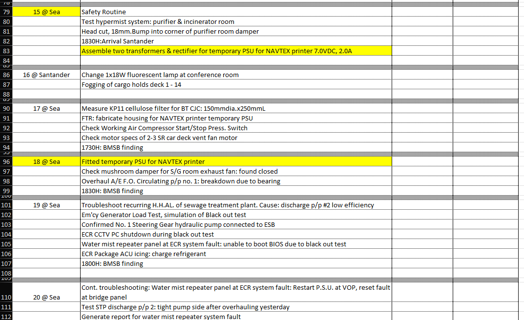
I fitted the entire makeshift PSU assembly inside the Bridge Central console. The enclosure kept the components secured, contained, and away from bridge crew interference. The supply was tapped from the 220V breaker panel at breaker 2F24, properly labelled: NAVTEX PRINTER.
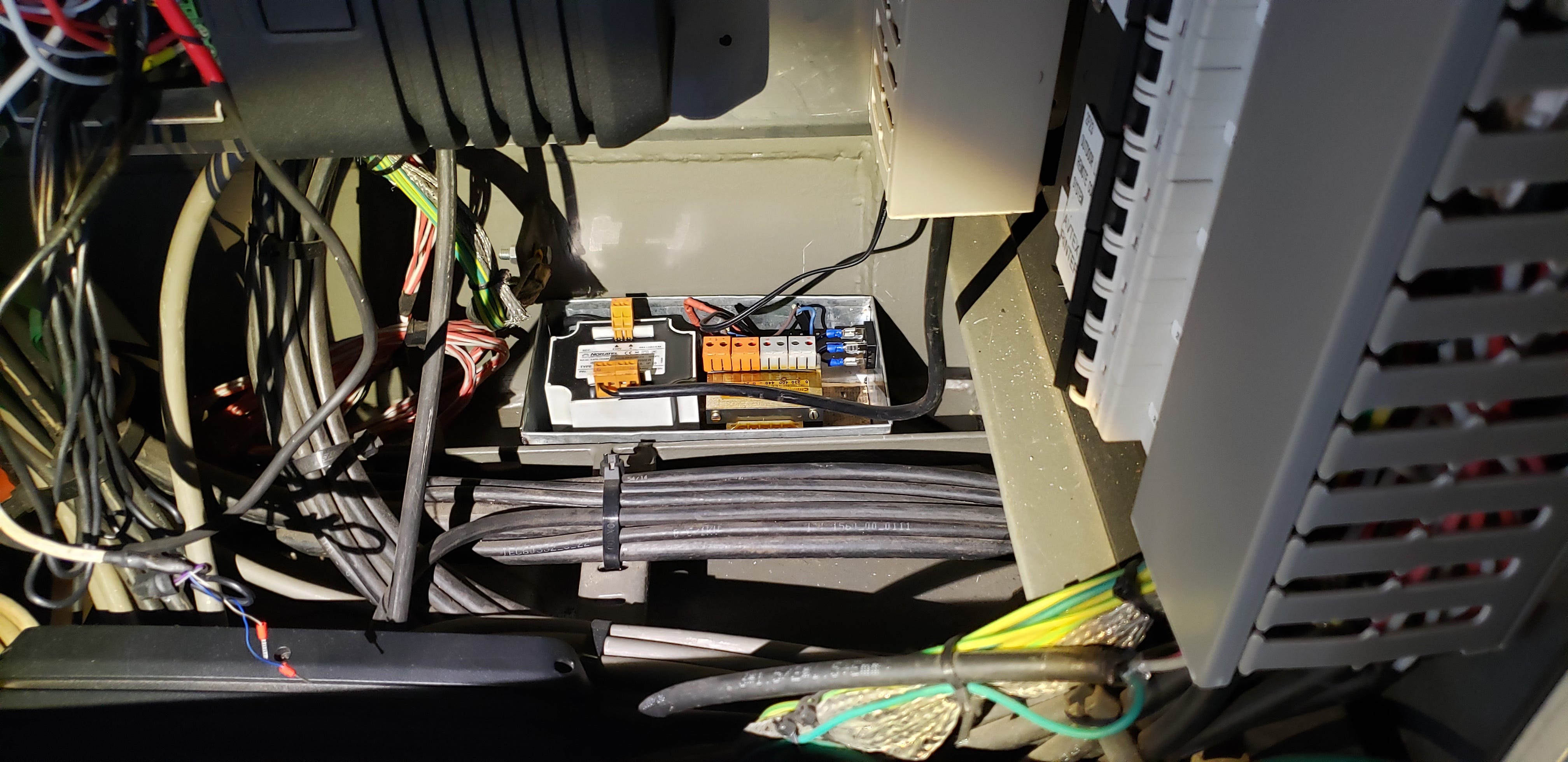
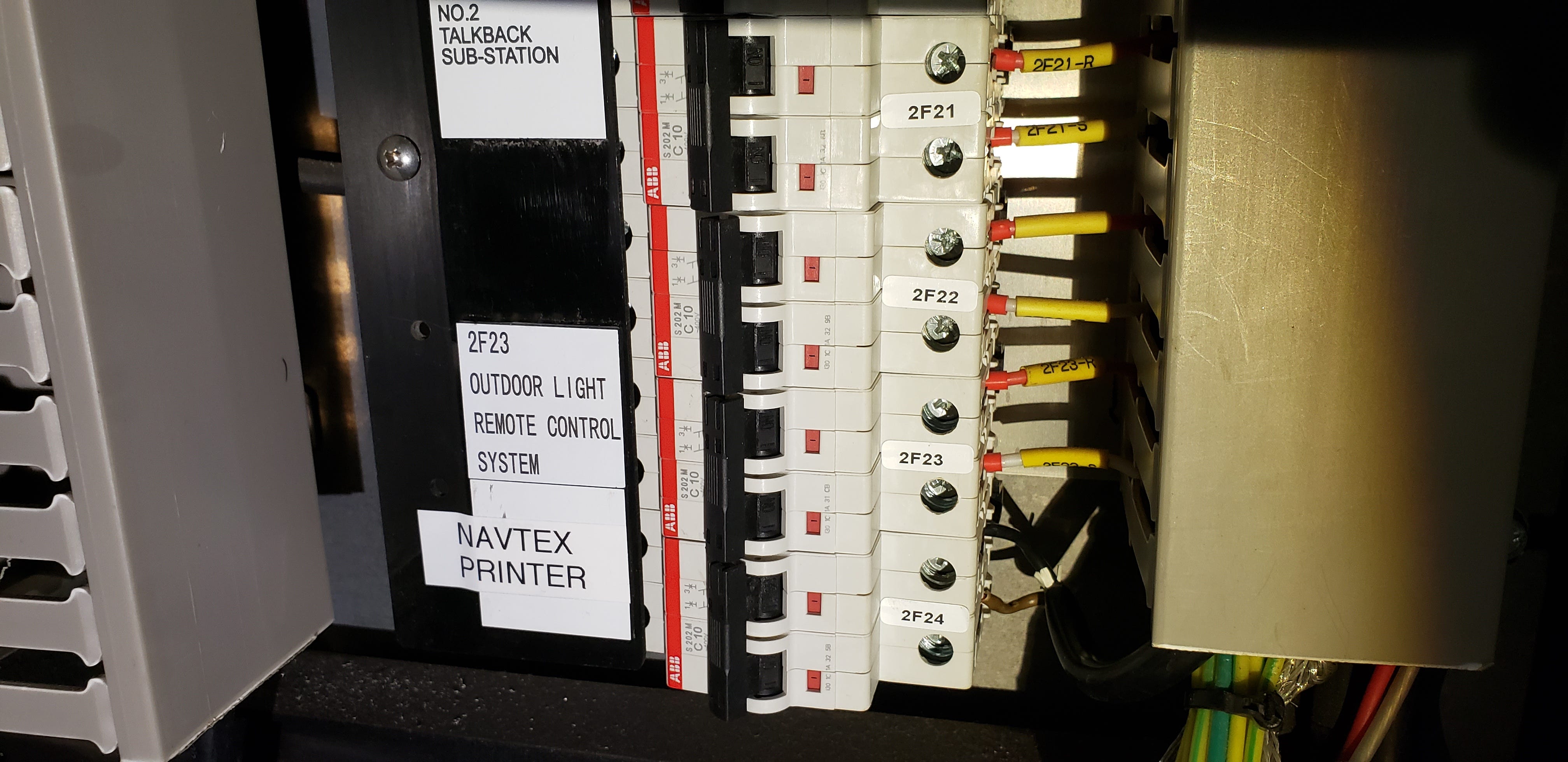
The Navtex printer powered up. The JRC NCR-333 resumed printing maritime safety information. NAVTEX communications: restored.
I do not have a photo of the printer running. Honest admission... by the time the final connections were made, and I confirmed the printer was functional, I had already moved to the next task. Busy watch. Photo forgotten. But the printer worked. It printed. And it kept printing.
The Outcome and The Wait
The OEM PSU was still on order when I signed off from the vessel. The makeshift unit held its post from May 18, 2021 through the remainder of my contract... keeping the NAVTEX printer operational and the vessel in compliance with SOLAS communication requirements.
Temporary does not mean careless. Temporary means: controlled, understood, functional, and documented.
That last line from my work log was not resignation. It was confidence. I built something that worked within the required electrical parameters, installed it safely, documented it completely, and tagged it properly. The OEM spare is the permanent solution. But the ship does not wait for procurement timelines to stay compliant.
Keep on Probing
This case came from before ProbeLem existed. But the mindset was already there.
Engage first with your mind, before your hands.
I did not pick up tools and start wiring random transformers together. I understood what the printer needed: 6.5V DC, 2.0A. I understood what I had available: non-standard transformer secondaries, spare bridge rectifiers left over from a different job. I did the math on what tap combinations could approximate the required voltage. I tested, measured, adjusted, and confirmed before installing.
The solution was in the problem itself. The printer needed a supply that did not exist as a standard spare. So I built one from what the ship already carried.
That is what a problem solver does… Probing right into the problem!
Keep on probing.
-Lem | https://probelem.substack.com
ProbeLem is a troubleshooting library built from real shipboard electrical work, diagnostics, and field reflection.
If this post helped, follow the blog for future case studies and leave a comment with the fault, system, or lesson you want explored next.

Comments
Post a Comment