How I Solve Any Electrical Problems
In 1934, philosopher Karl Popper published Logik der Forschung, later translated as The Logic of Scientific Discovery. It contains the best explanation I've found for how problems are actually solved. If you translate his heavy academic philosophy into a practical framework, it looks like this:
1. Notice a problem - You notice something doesn’t work or conflicts with what you expected.
2. Create a guess (Conjecture) - An explanation that is specific and risky.
3. Test your guess (Refutation) - Don’t look to confirm your guess, look to test it with:
A. Logic test - Look to spot contradictions.
B. Reality test - Run an experiment.
4. Eliminate errors - If your guess fails the tests, improve it or discard it.
5. Repeat - You’re back at step 1 making a new guess with the lessons learned. Or you’ve solved it, and moved onto a new, bigger, and better problem.
Five steps. Clean. Logical. Academically unassailable.
I respect Popper. But I work on ships, not in a laboratory. And when you’re troubleshooting a real fault on a real vessel, you need something you can loop inside your head under pressure.
I simplify Popper’s ideas into something I can loop in my head:
Identify. Probe. Steer/Correct.
I call it the Probing Loop:
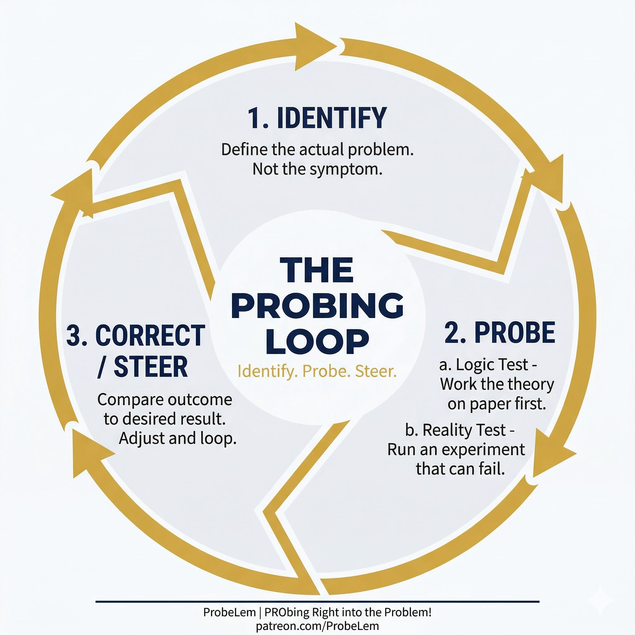
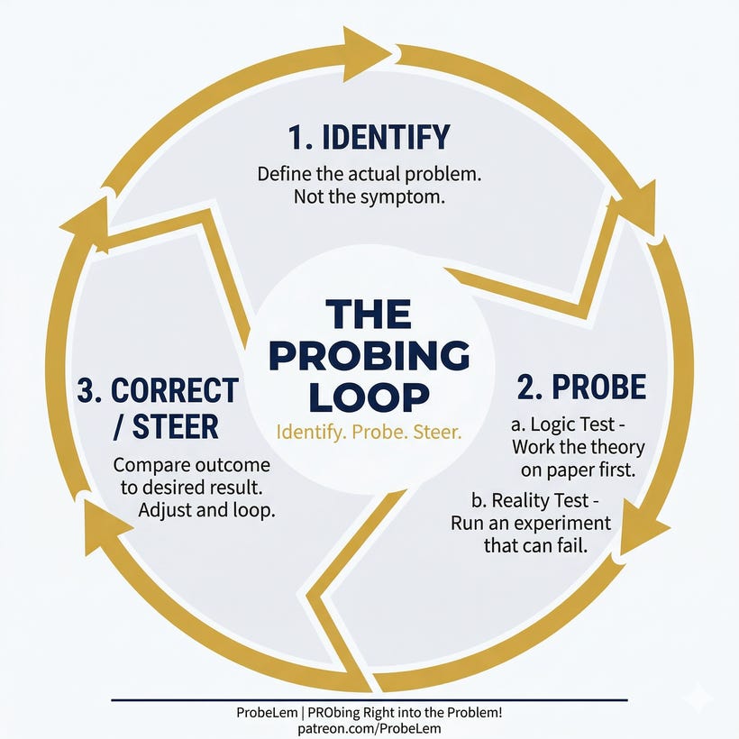
1. Identify the Problem - Define the actual problem. Not the symptom. The problem.
2. Probe (investigate)
a. Logic test - Work the theory on paper first. Spot contradictions before you touch anything.
b. Reality test - Run an experiment that can fail. Let the system tell you if you’re right.
3. Correct/Steer (Cybernetics) - Compare the outcome to the desired result. If you’re off course, adjust and loop again.
The difference between Popper and me is not the steps. It is what happens when a step fails.
Popper says: eliminate the failed guess and start over. Surgical. Cut and restart.
I say: steer. The failed attempt is not a dead end. It is a compass reading. You don’t throw away the rudder because the ship drifted 2° off course. You correct the heading.
His method is surgical. Mine is navigational.
And the reason I had to build this framework is because I discovered the alternative. A cycle that looks like problem-solving but converges on nothing. I call it the Doom Loop.
Before I show you the Probing Loop in action, you need to understand the Doom Loop. Because every troubleshooter, at every decision point, is choosing between the two. Whether they realize it or not.
THE DOOM LOOP
The Doom Loop is not a character flaw. It is the default human response under pressure.
You see a symptom. You assume you already know the cause. You swap a part. It fails again. You swap another part. It fails again. You blame the equipment, blame the manufacturer, write it up as “intermittent fault, monitor.” The spare parts are gone. Nothing has changed.
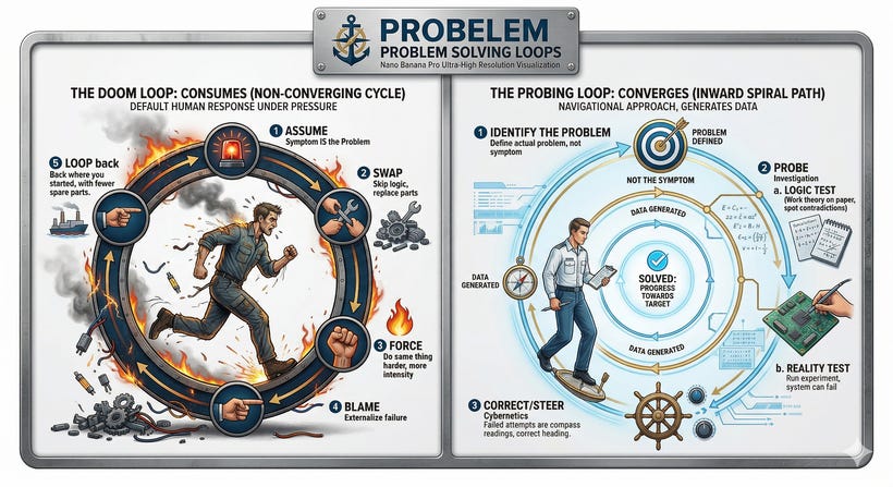
The Doom Loop has five beats:
1. Assume - Skip identification. The symptom IS the problem. “The breaker is faulty.”
2. Swap - Go straight to replacing parts. No logic test. No paper work. Just change it. “If I replace this, it should work.”
3. Force - When the swap doesn’t work, do the same thing harder. Same approach, more intensity. “It has to be this. Try again.”
4. Blame - When forcing doesn’t work, externalize. “The manufacturer sent a bad part.” Or: “This vessel is cursed.” Or the classic: “It was working before I got here.”
5. Loop back to Assume - No new information was gathered at any step. You are back where you started, with the same assumptions and fewer spare parts.
The Doom Loop is seductive because it feels like action. You are busy. You are doing things. You are opening panels, pulling fuses, swapping components. It looks like troubleshooting. But at no point did you generate new information about the system. You consumed resources and produced nothing new.
The Probing Loop is the opposite. Even when it fails, it generates data. A failed logic test tells you which theory to discard. A failed reality test narrows the search space. A correction that falls short tells you the direction is right but the magnitude is wrong. Every step moves you closer, even the ones that don’t work.
The Doom Loop consumes. The Probing Loop converges.
Now let me be honest about something. The Doom Loop is not just for inexperienced engineers. It catches everyone.
The cadet Doom Loops because he doesn’t know where to start, so he starts with whatever he can touch. That is inexperience.
The senior ETO Doom Loops because he has seen a hundred faults and assumes this one is the same. That is overconfidence.
The time-pressured officer Doom Loops because the bridge is waiting, the maneuver is coming, and there is no time to sit with a diagram. That is stress.
Three different people. Three different reasons. Same loop. Same result.
What separates them from the Probing Loop is not intelligence. It is not experience. It is one decision, made in the first ten seconds after the alarm sounds:
Do I react, or do I identify?
There is a line I keep coming back to, one I wrote for myself years ago:
Engage first with your mind, before your hands.
That is the exit from the Doom Loop. That single pause. Not a long pause. Not a meditation. Just enough time to ask: what is actually happening here? Not what do I think is happening. Not what happened last time on a different vessel. What is the system telling me right now?
That pause is the entrance to the Probing Loop.
THE FIELD PROOF
Let me show you exactly how the Probing Loop works in the real world, using one of the most frustrating mysteries I ever faced on board a vessel.
The case of the mismatched UVT coil.
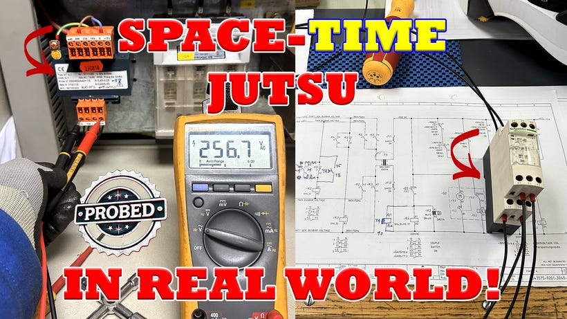
Full documentary of this case: ProbeStudy #03 - The Case of the Mismatched UVT Coil. Click the video links below:
How UVT Coil Impedance Mismatch Caused MCCB Nuisance Tripping | #PRObed Part 1 | Marine Electrical
How We Tried (And Failed) to Fix UVT Coil Impedance Mismatch, Series Part 2 | 1st Try |Traveling ETO
Space-Time Jutsu: The Final Solution to MCCB UVT Nuisance Tripping | 93m Full Uncut Troubleshooting
The Setup
We had a 28-year-old chemical tanker with a Merlin Gerin circuit breaker (Q4) on the main 440V switchboard. The breaker finally failed mechanically. End of life. The previous ETO replaced it with a modern Schneider Electric NSX 400N series and signed off the vessel. On paper, it was the correct replacement. Same frame. Same rating. Same function.
But after the replacement, every time we opened the bus-tie breaker to enter split mode, the new breaker tripped. Fuses F7 through F10 on the control circuit started blowing intermittently. The problem persisted for roughly a year before I joined the vessel.
That is where the two loops diverge.
Probing Loop, First Pass
1. Identify the Problem
The Doom Loop response to this situation is simple: “The breaker is faulty. Order another one.”
The Probing Loop asks a different question. Not “what is broken?” but “what condition triggers the fault?”
The symptom was the breaker tripping. But tripping is what breakers do. The question is: what makes it trip specifically when entering split mode?
I narrowed it down. The breaker did not trip randomly. It tripped specifically when the bus-tie breaker opened. That specificity matters. Random tripping suggests a component failure. Conditional tripping suggests a system interaction.
The problem was not “the breaker trips.” The problem was “something in the split mode transition causes the UVT (undervoltage trip) coil to see a voltage condition that commands the breaker to open.”
That is a completely different starting point. And the Doom Loop never gets there, because it never asks the question.
2. Probe (Investigate)
2a. Logic Test
The Doom Loop response: “Check the wiring. Swap the fuse. Tighten the connections.”
The Probing Loop response: Work the theory on paper first. Open the theoretical theatre.
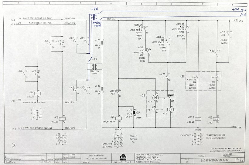
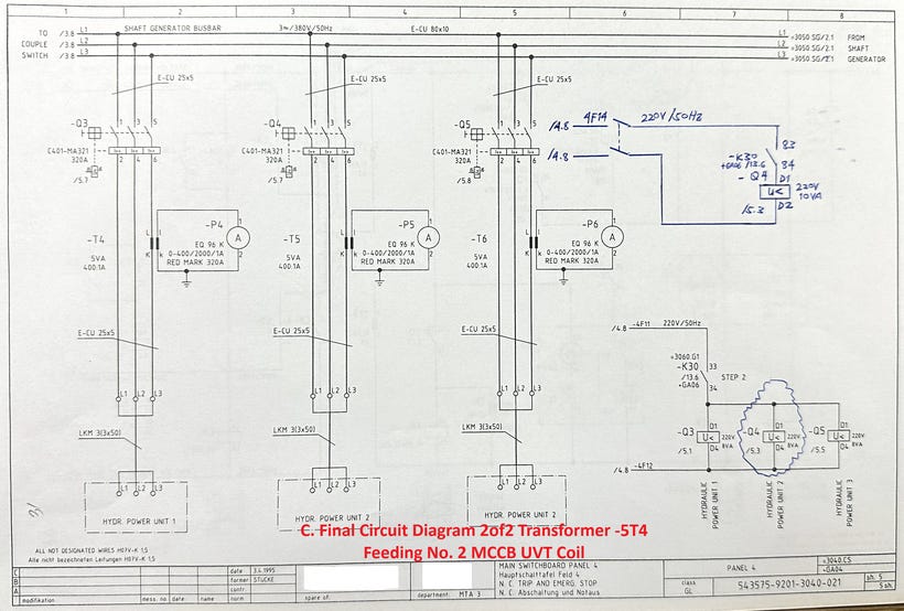
Before I touched a single wire, I sat with the electrical drawings. I documented the control circuit in real-time. I treated the drawing like a stage, and every component was an actor with a role.
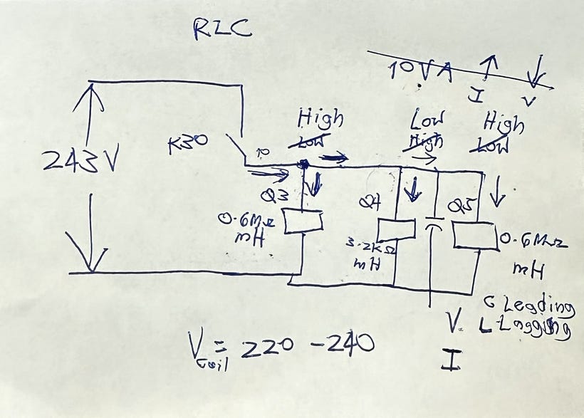
I applied Kirchhoff’s Current Law (KCL) to the shared control transformer loop. The old Merlin Gerin UVT coil and the new Schneider UVT coil were both connected to the same control voltage source, in parallel with other loads. In a parallel circuit, current distributes according to impedance. Lower impedance draws more current.
I calculated the AC impedance using Ohm’s Law for AC circuits: Z = V/I. But because we were dealing with coils, not just resistors, I could not use DC resistance alone. A coil has both resistance (R) and inductive reactance (XL). The total impedance is a complex number: Z = R + jXL. This is where most troubleshooters stop, because complex numbers feel like textbook theory. But on this vessel, complex numbers were the only tool that revealed the truth.
The logic test exposed a massive contradiction.
The old Merlin Gerin UVT coil: high impedance. Approximately 0.7 MΩ. High resistance, low inductance. A passive, well-behaved load that drew almost no current from the shared source.
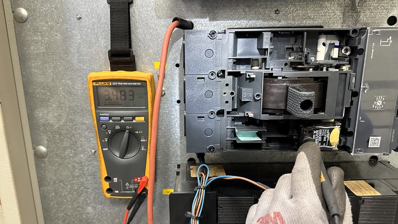
The new Schneider UVT coil: low impedance. Approximately 3.48 kΩ. Low resistance, high inductance. An active, hungry load.
That is a 200-times difference in impedance.
In a parallel circuit mixing passive and active components, this new low-impedance coil acted as a current sink. During the split mode transition, when the bus-tie breaker opens, there is a microscopic voltage transient on the control bus. The old coil would have ignored it. The new coil, with its low impedance and high current draw, amplified the disturbance. It pulled the control voltage below the UVT threshold. The breaker saw undervoltage and did exactly what it was designed to do. It tripped.
The breaker was not faulty. It was obedient. The fault was in the system interaction that nobody had analyzed.
2b. Reality Test
The logic test gave me a theory: the parallel shared source is the enemy. The new coil’s low impedance is pulling down the control voltage during the split mode transient.
But a theory on paper is still just a theory. I needed the system to confirm it.
We designed a simple reality test. We physically removed the new UVT coil from the shared control transformer entirely. We plugged it into a completely separate power source using an extension cord from another socket. Total isolation. No shared path.
We ran the split mode operation. The bus-tie opened.
The breaker held. Zero trips.
The reality test confirmed the logic test. The parallel shared source was the root cause. Not the breaker. Not the coil. Not the wiring. The interaction between a new component and an old system architecture.
3. Steer/Correct
The Doom Loop response to a successful test: “Problem solved. Write it up. Move on.”
The Probing Loop response: Compare the outcome to the desired result. An extension cord is not a permanent solution.
Our desired outcome: the breaker holds during split mode, permanently, without external workarounds.
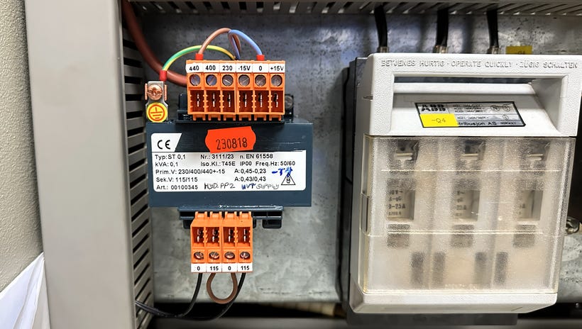
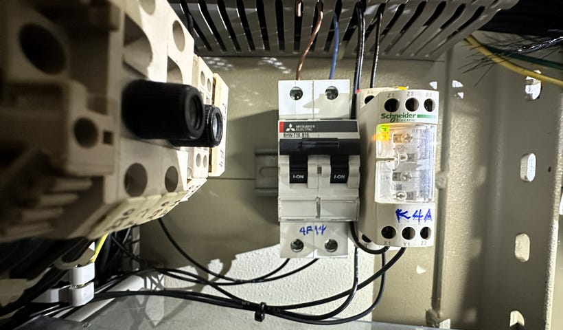
Our correction: install a dedicated 440V/440V isolation transformer (T4) with its own fuse (F14) to permanently separate the new UVT coil from the shared control bus. Spatial domain separation. Give the coil its own clean power source so it never sees the shared current path during the bus-tie transition.
I call this the Space Jutsu.
We ran the test. The breaker still tripped. But we have new information to steer the solution forward.
The compass reads closer to 045° than before. But not 045°.
The Doom Loop engineer quits here. “We tried isolation and it didn’t work. The breaker must be faulty after all.”
The Probing Loop reads the compass and feeds the error back to a new Identify. The first pass is complete. The loop restarts.
Probing Loop, Second Pass
1. Identify the Problem (Refined)
The spatial fix did not solve the tripping but did the course to pursue it. That tells me: the direction was right, but the solution was incomplete.
The voltage transient during the bus-tie opening happens on the primary main bus. The isolation transformer blocks the shared current path, but its primary is still connected to that bus. The transient passes through T4 to the secondary side. The transformer solved the spatial problem. But the event is not only spatial. It is also temporal. A millisecond-scale voltage dip.
New problem identified: the transient has two dimensions. Space and time. We only addressed one.
2. Probe (Logic + Reality)
If isolating the coil in three-dimensional space was not enough, we had to address the fourth dimension. Time.
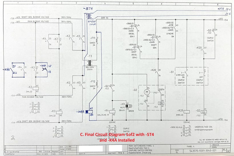
The logic: add a component that holds the UVT coil energized through the transient duration. An off-delay timer relay (K4A), set to 1.0 second. When the control voltage dips during the split mode transition, the timer buffers the circuit. It holds the coil powered for one additional second. By the time the timer expires, the voltage has stabilized. The UVT coil never sees the dip.
The reality test: we kept the isolation transformer and added the off-delay timer. We ran the split mode operation.
Zero trips. We ran it again. Zero trips. And again.
3. Steer/Correct
Desired outcome achieved. The compass reads 045°.
I call the complete solution the Space-Time Jutsu. Spatial domain separation (isolation transformer T4) plus temporal domain separation (off-delay timer relay K4A). Neither solution worked alone. Both together: zero unwanted trips.
The first loop was not a failure. It was the compass reading that made the second loop possible.
YOU ALREADY KNOW THIS
The word “cybernetics” comes from the ancient Greek kybernētikos, meaning “good at steering.” Norbert Wiener formalized it in 1948 as the study of control and communication in systems. But the concept is as old as seafaring itself. It is how a helmsman steers a ship.
I introduced the autopilot analogy in the field proof above. But I want to push it further, because if you are an ETO or a marine engineer, you already live inside cybernetic systems every day. You just might not call them that.
The Power Management System on your vessel is a cybernetic loop. The PMS reads actual bus frequency and voltage. It compares them to the desired setpoints. The difference is the error signal. The system responds: adjust generator load sharing, connect or disconnect a generator, shed non-essential loads. Continuously. Not once. In a loop.
The engine governor is a cybernetic loop. The Magnetic Pickup Unit reads actual RPM from the flywheel teeth. The governor compares it to the desired speed setpoint. The error signal drives the fuel rack actuator. Too slow: more fuel. Too fast: less fuel. Continuously. In a loop.
The AVR (Automatic Voltage Regulator) is a cybernetic loop. The sensing circuit reads actual generator terminal voltage. The AVR compares it to the desired voltage. The error signal adjusts the excitation current. Continuously. In a loop.
You understand these systems. You troubleshoot them. You trust them. When the PMS sheds load, you do not say “the system panicked.” You say “the system corrected.”
The Probing Loop asks you to apply the same trust to your own thinking.
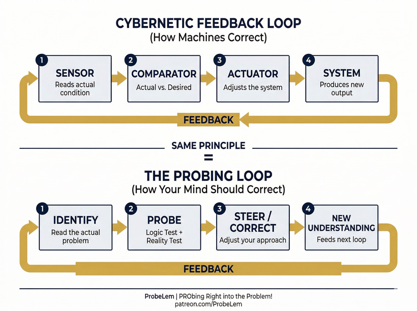
Identify is the sensor. It reads the actual condition. Probe is the comparator. It tests actual against expected using logic and reality. Steer/Correct is the actuator. It adjusts your approach based on the error signal.
Your mind can run in closed-loop or open-loop. The Probing Loop is closed-loop: every output feeds back as input for the next pass. The Doom Loop is open-loop: no feedback, no correction, no convergence. Just the same action repeated with the same assumptions.
You would never design a governor without feedback. Do not run your troubleshooting mind without it either.
THE ESCAPE HATCH
If the Doom Loop is the default under pressure, there has to be a way out. A reset. A moment where the engineer recognizes the loop and breaks it.
In my experience, the exit is not dramatic. It is not a sudden insight or a flash of genius. It is a quiet moment where you stop and admit: I do not actually know what is causing this.
That admission is the hardest part. Especially if you are experienced. Especially if you have been an ETO for 15 years and you feel like you should know. The ego says: keep going, you’ll figure it out. The Doom Loop feeds on that.
The escape hatch is the willingness to go back to Step 1. Identify. Not the symptom. The actual problem. And to do that, you have to let go of the assumption you have been carrying.
In the MCCB case, the assumption that had persisted for a year was: the replacement breaker is the problem. The escape hatch was a different question: what if the breaker is working correctly, and the problem is what it is connected to?
That single reframe moved the entire investigation from the Doom Loop to the Probing Loop.
I do not have a formula for when the escape hatch opens. But I have one rule that has never failed me:
Engage first with your mind, before your hands.
When I catch myself reaching for a tool before I have a theory, I stop. That impulse is the Doom Loop pulling. The pause is the exit.
THE LOOP NEVER ENDS
There is one more thing Popper got right, and it is the part most people skip over.
Step 5 of his framework: Repeat. “You’re back at step 1 making a new guess with the lessons learned. Or you’ve solved it, and moved onto a new bigger and better problem.”
That last line is important. Solving a problem does not end the loop. It starts a new one.
When we solved the MCCB UVT tripping, the immediate problem was closed. Zero trips. Desired outcome achieved. But the solution itself opened a new set of questions. Why did the manufacturer’s replacement coil have such radically different impedance characteristics? Is this a known issue across Schneider NSX series retrofits on older Merlin Gerin switchboards? How many other vessels are running the same mismatch without knowing it?
And beyond the technical: how do I document this so the next ETO who faces it does not spend a year in the Doom Loop?
That last question is the one that led to ProbeStudy No. 03. A three-part video documentary. And eventually, to this article.
The Probing Loop is fractal. Every solution is the Identify step of a new, bigger loop. You solve the fault. Then you solve the documentation problem. Then you solve the knowledge-sharing problem. Then you solve the education problem. Each loop builds on the one before it.
That is not exhausting. That is the craft.
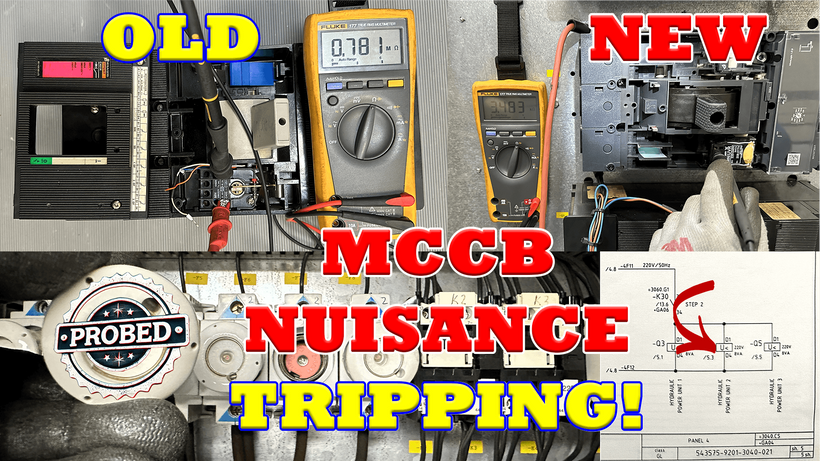
The full three-part documentary of this case: ProbeStudy #03. Click the video links below:
How UVT Coil Impedance Mismatch Caused MCCB Nuisance Tripping | #PRObed Part 1 | Marine Electrical
How We Tried (And Failed) to Fix UVT Coil Impedance Mismatch, Series Part 2 | 1st Try |Traveling ETO
Space-Time Jutsu: The Final Solution to MCCB UVT Nuisance Tripping | 93m Full Uncut Troubleshooting
The Probing Loop:
1. Identify the Problem - Define the actual problem. Not the symptom. The problem.
2. Probe (investigate)
a. Logic test - Work the theory on paper first.
b. Reality test - Run an experiment that can fail.
3. Correct/Steer (Cybernetics) - Compare outcome to desired result. Adjust and loop again.
The Doom Loop consumes. The Probing Loop converges.
I never understood learning... until I experienced it. I never found clarity... until I taught it.
I am documenting real-world electrical knowledge I wish existed when I was starting out.
— Lem | Traveling Fleet ETO | ProbeLem
PRObing Right into the Problem!
ProbeLem is a troubleshooting library built from real shipboard electrical work, diagnostics, and field reflection.
If this post helped, follow the blog for future case studies and leave a comment with the fault, system, or lesson you want explored next.

Comments
Post a Comment