ProbeStudy No. 02: Control Transformer Power Cycling | Understanding Inrush and Core Magnetization Behavior | Part 2
#ProbeTips #ElectricalTroubleshooting #ControlTransformer #InrushCurrent #ShipCrane #MaritimeEngineering
The Breakthrough
Systematic Isolation:
Step 1: Disconnect primary wires from -T1 transformer terminals (0V and 400V)
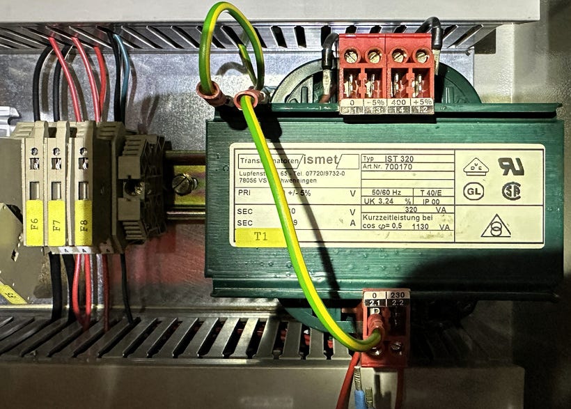
Measured wire-to-wire resistance: OL MΩ ✓ (no short in supply wiring)
Measured transformer terminal-to-terminal resistance: 7.5Ω ✓ (matches nameplate)
Step 2: Check fuse holder integrity
Measured resistance across F4-F5 fuse sockets (empty): OL ✓ (no phantom current path)
Step 3: Reconnect and verify
Reconnected wires to -T1 primary terminals
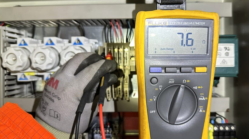
Measured resistance across F4-F5 positions (with transformer connected): 7.6Ω
This is correct: measuring through transformer primary winding
0.1Ω difference from 7.5Ω is wire resistance + connection resistance (normal)
Step 4: Test energization
Replaced F4 (6th fuse used so far)
Took a breath
Closed Q1
No immediate fault sound.
Checked panel: Both F4 and F5 intact. No blown fuses.
SUCCESS.
Wait... what? I didn’t change anything. I just disconnected, measured, and reconnected the same wires. Why does it work now?
Step 5: Restore secondary circuit
Q1 OFF
Reconnected all secondary wiring
Left F6, F7, F8 still removed (isolated for safety)
Q1 ON
Measurements:
Primary voltage present: 400V ✓
Secondary voltage: 230V ✓
No fuse failures ✓
Step 6: Full restoration
Closed F6 (control loads) — good
Closed F7 (space heaters) — good
Closed F8 (24VDC supply) — good
All control loads operational
Crane limit switches responding correctly
System fully functional
Total casualties: 5 fuses destroyed (F4 ×3, F5 ×2)
Actual equipment fault: None. Everything was healthy all along.
WHAT REALLY HAPPENED
The Invisible Enemy: Magnetizing Inrush Current
This wasn’t a short circuit. This wasn’t a wiring error. This was a transient electromagnetic phenomenon that occurs during transformer energization.
Normal Operation Math:
Control transformer -T1 steady-state primary current:
I = Power / Voltage I = 320VA / 400V = 0.8A
Fuse rating: F4 and F5 = 2A
Safety margin: 2A / 0.8A = 2.5× overrated (appropriate for continuous duty)
So why did 2A fuses blow with only 0.8A load?
THE PHYSICS BEHIND IT
What is Magnetizing Inrush Current?
When you energize a transformer, the iron core must be magnetized before it can transfer power. This magnetization process creates a massive transient current spike that can reach:
10 to 40 times the steady-state current
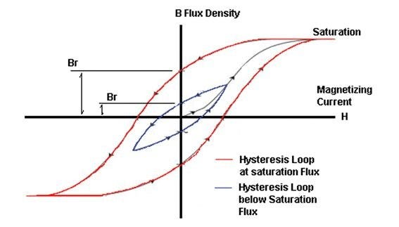
For our transformer:
Steady-state: 0.8A
Inrush: 8A to 32A (for 10-50 milliseconds)
Why didn’t the fuses handle this?
Fuses operate on I²t rating (energy over time). Even though inrush is brief, if you:
Close the switch at an unfavorable phase angle
Have high remanent flux in the core
Attempt energization multiple times in quick succession
...the accumulated thermal stress can blow the fuse even though no single event would.
The Role of Remanent Flux
What is it? When you de-energize a transformer, the iron core retains residual magnetism called remanent flux. Think of it like a permanent magnet that slowly fades. Transformer remanent flux is a residual magnetic flux that remains in a transformer’s core after it has been de-energized. When the transformer is re-energized, this trapped flux, if it has the same polarity as the new applied flux, can cause a very high, temporary inrush current that can be damaging.
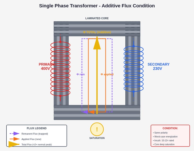
Why does it matter? When you re-energize, the startup magnetizing current depends on:
The polarity of remnant flux (North/South orientation)
The phase angle when you close the switch (where in the AC sine wave)
Whether remnant flux aids (additive) or opposes (subtractive) the new magnetizing flux
Best case scenario:
Switch closes at voltage zero-crossing
Remnant flux opposes new flux
Core doesn’t saturate deeply
Inrush stays low (~5-8A)
Fuse survives
Worst case scenario:
Switch closes at voltage peak (90° or 270°)
Remnant flux aids (additive) new flux
Core saturates heavily
Inrush skyrockets (25-40A)
Fuse blows
My first 3-4 attempts: Unlucky combination of high remnant flux + bad phase angle timing
Why Disconnecting the Wires “Fixed” It
This is the fascinating part - I accidentally performed an unintentional demagnetization procedure:
What happened during troubleshooting:
Time delay: While measuring, testing, and thinking, several minutes passed
Remanent flux slowly decayed through hysteresis losses
Each minute reduced the remnant flux by a small percentage
Mechanical disturbance: Removing and reconnecting wires
Physical vibration disturbed magnetic domain alignment in core
Slightly randomized the remnant flux polarity
Lucky timing: Final re-connection and switch closure
Happened to close Q1 at a more favorable phase angle
Reduced remnant flux no longer aided worst-case saturation
Inrush stayed within fuse I²t withstand capability
I didn’t fix anything. I just got lucky with timing and flux decay.
Point-on-Wave Switching
The AC voltage sine wave matters:
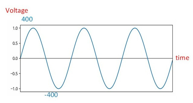
If switch closes here: ↓
At zero-crossing (0V): Minimal inrush
At peak (±400V): Maximum inrush
You have no control over this with a manual disconnect switch - it’s purely random based on the instant you flip the handle.
Advanced systems use:
Zero-crossing detection relays (close only at 0V point)
Soft-start contactors (pre-insertion resistance)
Controlled closing mechanisms (motor-driven, timed closure)
LESSONS FOR THE FIELD
For ETOs Troubleshooting Similar Issues:
1. Don’t panic when control transformer fuses blow on first energization after shutdown
Inrush is a normal phenomenon, not necessarily a fault
Most common after extended de-energization (days/weeks)
2. Fuse sizing for control transformers:
Steady-state calculation: I = VA / V
Use slow-blow (time-delay) fuses rated 3-4× steady-state current
For 0.8A steady-state → 3A or 4A fuses would be more appropriate than 2A
Fast-acting fuses are vulnerable to inrush nuisance blowing
3. If fuses blow repeatedly on energization:
Wait 5-10 minutes between attempts (allow remnant flux to decay)
Don’t rapid-cycle the switch (accumulates thermal stress in fuses and transformer)
Check for actual faults first (insulation resistance, winding continuity)
Consider active demagnetization techniques (see Advanced Techniques below)
4. Thermal imaging after successful energization:
Inrush stress can reveal marginal connections
Hot spots on terminals indicate high-resistance joints that worsened during high current
Good time to inspect for loose hardware
5. Measurement interpretation:
Low winding resistance (single-digit ohms) is normal for power transformers
Don’t confuse DC resistance with AC impedance
Trust nameplate ratings - if measured values match, winding is likely healthy
For System Designers:
1. Control transformer primary protection:
Account for 10-15× inrush when selecting fuses
Use slow-blow (gL/gG) fuses not fast-acting (aM) types
Consider 3-4A fuses for sub-1A steady-state loads
2. Inrush mitigation for critical systems:
NTC thermistors: Self-resetting inrush limiters (cold = high R, hot = low R)
Pre-insertion resistors: Temporary resistance during first 100ms
Soft-start relays: Zero-crossing detection and controlled closure
Higher VA transformers: Larger core = lower flux density = lower inrush
3. System coordination:
Avoid energizing multiple transformers simultaneously
Stagger startup sequences in automated systems
Consider transformer switching transients in coordination studies
ADVANCED TECHNIQUES
Active Demagnetization Methods
If you encounter this issue repeatedly, here are professional techniques to rapidly eliminate remanent flux:
Method 1: Primary Terminal Shorting
Procedure:
Verify Q1 is OFF and locked out (LOTO)
Verify zero voltage at primary terminals with multimeter
Use insulated jumper wire to short terminals 0V and 400V together
Leave shorted for 10 seconds
Remove jumper
Replace fuse if needed
Energize normally
Why it works:
Remanent flux induces voltage in primary winding
Short circuit provides path for induced current
Current flows in direction that opposes remnant flux (Lenz’s Law)
Energy dissipates as I²R heat in winding resistance
Time constant: L/R ≈ 0.2 seconds (extremely fast)
Safety considerations:
CRITICAL: Must verify de-energization first
Risk of catastrophic failure if accidentally energized while shorted
Use only with robust LOTO procedures
Consider this an expert technique requiring training
Method 2: Secondary Terminal Shorting (SAFER ALTERNATIVE)
Procedure:
Verify Q1 is OFF (LOTO)
Short secondary terminals 0V and 230V together
Leave shorted for 10 seconds
Remove jumper
Energize normally
Why it works:
Remanent flux links both primary and secondary windings (shared core)
Shorting secondary allows current in secondary winding
This creates opposing field in the same magnetic core
Demagnetizes both windings simultaneously
Time constant: slightly slower (~0.5s) but still very fast
Advantages over primary shorting:
✓ Working on lower voltage side (230V vs 400V) = safer
✓ Nearly as effective
✓ Less catastrophic if accidentally energized
✓ Recommended compromise between safety and effectiveness
Method 3: Resistive Demagnetization
Procedure:
Connect resistor (50-100Ω, 10W rating) across secondary terminals
Leave connected for 10-15 seconds
Remove resistor
Energize normally
Why it works:
Resistor provides controlled current path (not dead short)
Slower decay but still much faster than open circuit
Limits current if accidentally energized
Best for:
Training scenarios
High-value equipment (conservative approach)
Situations where dead short seems too risky
Method 4: Passive Decay with Secondary Loads Connected
What I could have done differently:
Instead of isolating F6, F7, F8 during troubleshooting:
Leave secondary loads connected during wait periods
Space heaters, control relays, etc. provide resistive path
Much slower than active shorting but faster than open circuit
Completely passive and safe
Decay time: Minutes instead of hours (vs disconnected) or seconds (vs shorted)
Why NOT Ground the Terminals?
Common question: “Can I just ground the primary to dissipate the flux?”
Answer: No - grounding does NOT demagnetize.
Why:
Grounding provides a voltage reference, not a current path
Effective demagnetization requires current through the winding itself
Ground connection is electrically isolated from winding-to-winding path
Result: Same as leaving disconnected (slow passive decay only)
Analogy: Grounding is like marking “sea level” on a water tank - it’s a reference point, but doesn’t drain the water. You need an actual flow path.
What creates demagnetizing current:
✓ Shorting terminal-to-terminal (through winding)
✓ Resistive load terminal-to-terminal (through winding)
✗ Grounding one or both terminals (no winding current path)
THE BIGGER PICTURE
Why This Matters
This case study illustrates a fundamental challenge in electrical troubleshooting: textbook knowledge meets real-world chaos.
What the textbooks tell you:
Transformer primary current: I = VA / V = 0.8A
Fuse rating: 2A (adequate margin)
Winding resistance: Low (normal for transformers)
What the textbooks don’t emphasize:
Magnetizing inrush can be 40× steady-state
Remanent flux persists for hours
Point-on-wave switching is random with manual disconnects
Fuses integrate thermal stress over multiple events
“Low resistance” doesn’t mean “short circuit” in inductive loads
The equipment wasn’t faulty. The wiring wasn’t wrong. The fuses weren’t undersized for steady-state.
But the transient behavior - invisible, millisecond-scale, dependent on magnetic history and random switch timing - created a problem that mimicked catastrophic failure.
What I’d Do Differently Next Time
If I encounter transformer fuse blowing on energization again:
First attempt blows fuse:
Don’t immediately assume fault
Wait 5 minutes before next attempt (flux decay)
Consider inrush as likely cause
Second attempt blows fuse:
Verify no actual faults (insulation resistance, ground faults)
If tests show healthy system, apply active demagnetization
Short secondary terminals for 10 seconds (safer than primary)
Should succeed on next attempt
Document for future reference:
Note which transformers are prone to inrush issues
Consider fuse uprating if nuisance blowing occurs regularly
Add procedure to SMS or TMM (Technical Management Manual) for this specific equipment
This approach would have:
Solved issue in 2 attempts instead of 4-5
Saved 2-3 fuses
Reduced troubleshooting time by 50%
Increased understanding immediately instead of through trial-and-error
CONCLUSION
Sometimes the best troubleshooting tool isn’t a multimeter.
It’s understanding what the multimeter can’t show you:
Transient phenomena occurring in microseconds
Magnetic fields trapped in iron cores
The difference between DC resistance and AC impedance
The accumulated thermal stress in protective devices
The random phase angle of switch closure
The “fix” in this case wasn’t a repair - it was time, physics, and accidental flux management.
This is what separates component-level troubleshooting from system-level understanding.
The crane works. The limit switches work. The transformer works.
But now I understand why it didn’t work at first - and that’s worth more than the four fuses it cost to learn.
TECHNICAL SPECIFICATIONS SUMMARY
Control Transformer -T1:
Rating: 320VA
Primary: 400V AC ±5%, 50/60Hz, 0.8A nominal
Secondary: 230V AC, 1.39A nominal
Primary winding resistance: 7.5Ω (measured, matches nameplate)
Secondary winding resistance: 4.1Ω (measured, matches nameplate)
Protection:
F4, F5: 2A Diazed fuses (primary protection) - consider upgrading to 3-4A slow-blow
F6, F7: 2A (secondary loads)
F8: 6.3A (DC power supply output protection)
Calculated Inrush (estimated):
Steady-state primary: 0.8A
Typical inrush: 8-12A (10-15× steady-state)
Worst-case inrush: 24-32A (30-40× steady-state)
Duration: 10-50ms initial spike, decays over 100-200ms
DISCUSSION QUESTIONS
For ProbeLem community:
Have you experienced nuisance fuse blowing on control transformers after extended shutdowns?
Do you size fuses for steady-state or transient current in control circuits?
Have you used active demagnetization techniques on ship transformers?
What’s your SMS/TMM procedure for energization after major electrical work?
Should we standardize on slow-blow fuses for all control transformer applications?
Keep on probing!
-Lem | ProbeLem
ProbeLem is a troubleshooting library built from real shipboard electrical work, diagnostics, and field reflection.
If this post helped, follow the blog for future case studies and leave a comment with the fault, system, or lesson you want explored next.

Comments
Post a Comment