ProbeStudy No. 02: Control Transformer Power Cycling | Understanding Inrush and Core Magnetization Behavior | Part 1
#ProbeTips #ElectricalTroubleshooting #ControlTransformer #InrushCurrent #ShipCrane #MaritimeEngineering
Have you ever re-energized a control panel — only to find your fuses blowing without a clear short circuit? You’ve checked everything twice. No shorts. No ground faults. Wiring is perfect. But every time you close that main disconnect—POP. Another fuse gone.
5 fuses down. Still no answer. That was exactly what happened when I modified a ship’s crane control circuit.
This is the invisible enemy that hides in your transformer core—and conventional troubleshooting can’t find it.
This is second Probe Study in the ProbeLem technical library — focused this time not on insulation faults, but on a deceptive transient phenomenon that mimics catastrophic failure.
SYSTEM: Combination 3T/1T Provision & MOB Crane
TASK: Limit Switch Modernization (Roller → Proximity Sensor)
COMPLICATION: 5 Blown Fuses After Successful Modification
ROOT CAUSE: Magnetizing Inrush Current + Remanent Flux
LESSON: Understanding Transient Behavior vs Steady-State Analysis
THE WORK
System Overview
Crane Type: Dual-capacity combination crane
1T MOB recovery (steel cable underneath arm)
3T provision handling (steel cable over arm)
Common arm structure, two independent hoisting systems
Electrical System:
Supply: 400V AC, 50Hz, 3-phase
Main disconnect: Q1 (isolator switch)
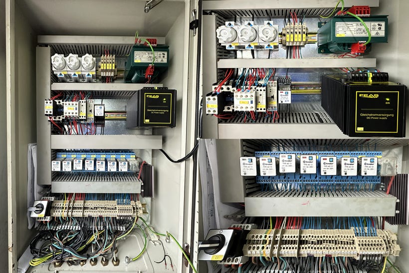
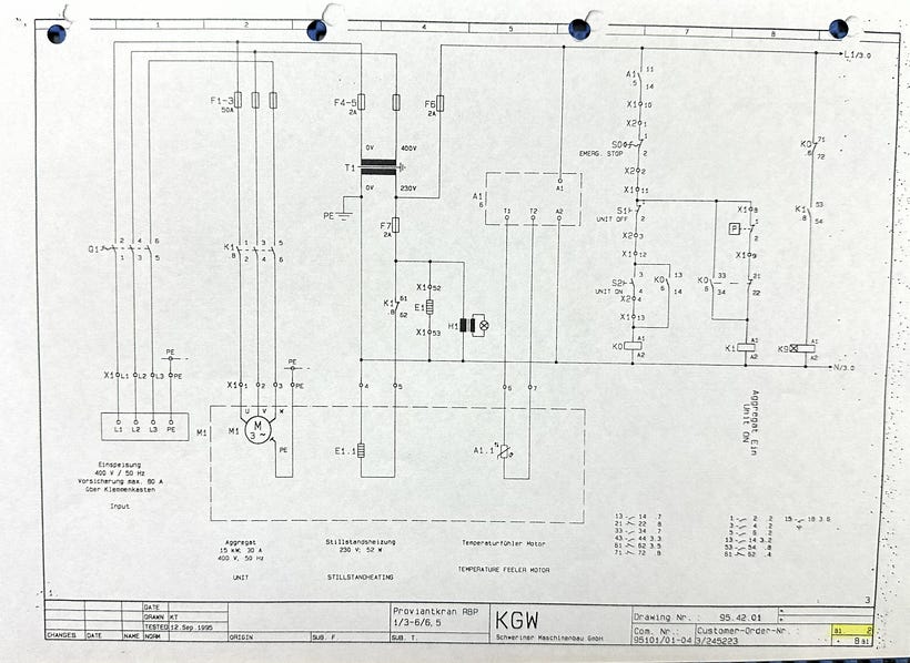
Power protection: F1, F2, F3 (50A) - feeds 15kW Hydraulic Aggregate Electrical Motor (30A rated)
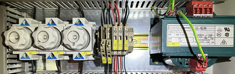
Control transformer: -T1 (320VA, 400V primary / 230V secondary)
Control protection: F4, F5 (2A) - transformer primary side
Secondary protection: F6, F7 (2A) - control loads and space heaters
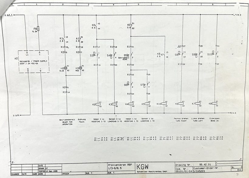
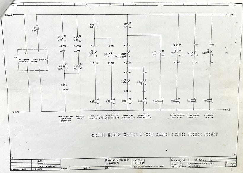
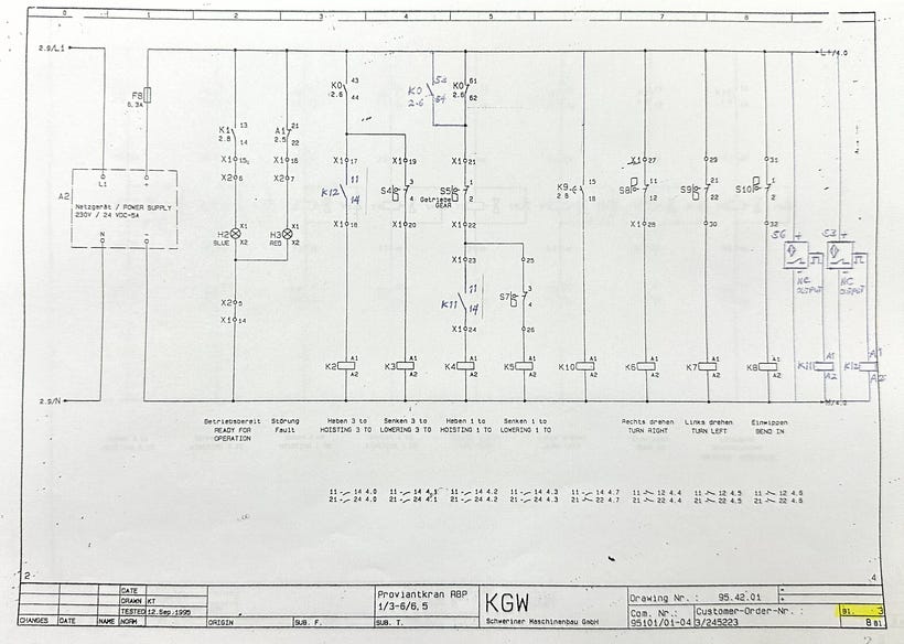
DC supply protection: F8 (6.3A) - 24VDC power supply output (230VAC → 24VDC, 5A)
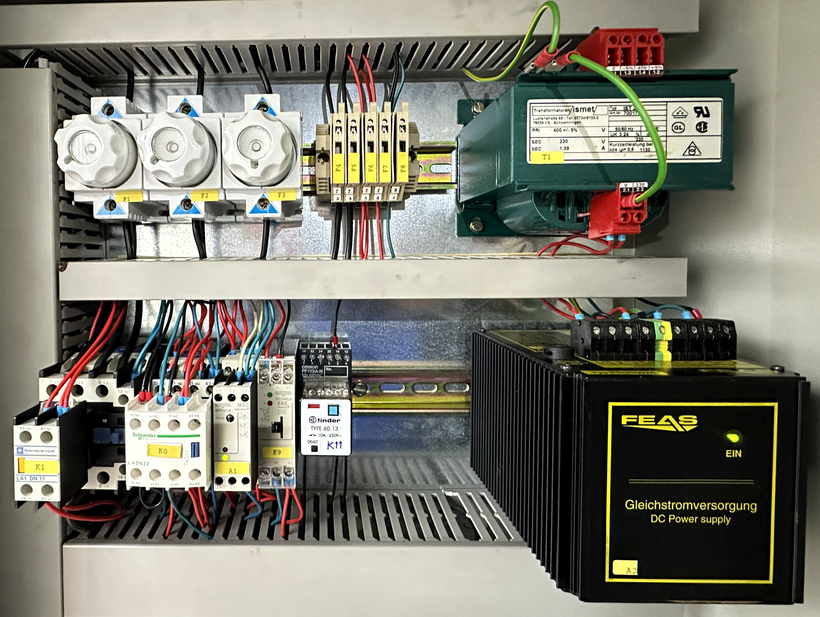
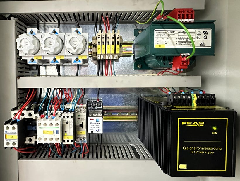
Image 03: Control transformer -T1 with fuse protection F4 and F5 (2A) for 400V primary, while F6-F8 protect various secondary loads.
The Modification Task
Original Configuration:
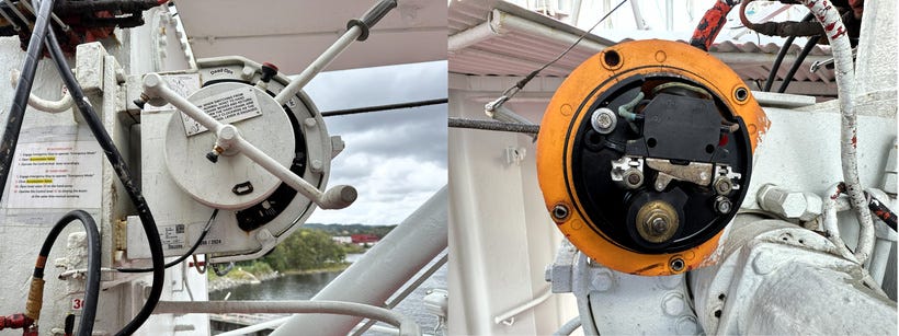
Hoisting limit switches: Mechanical roller-type (’S3’ for 3 Tons and ‘S6’ for 1 Ton)
Wiring: 2-wire (Common + N.O. contact terminals 13-14)
Logic: Contact opens when hoist reaches maximum height
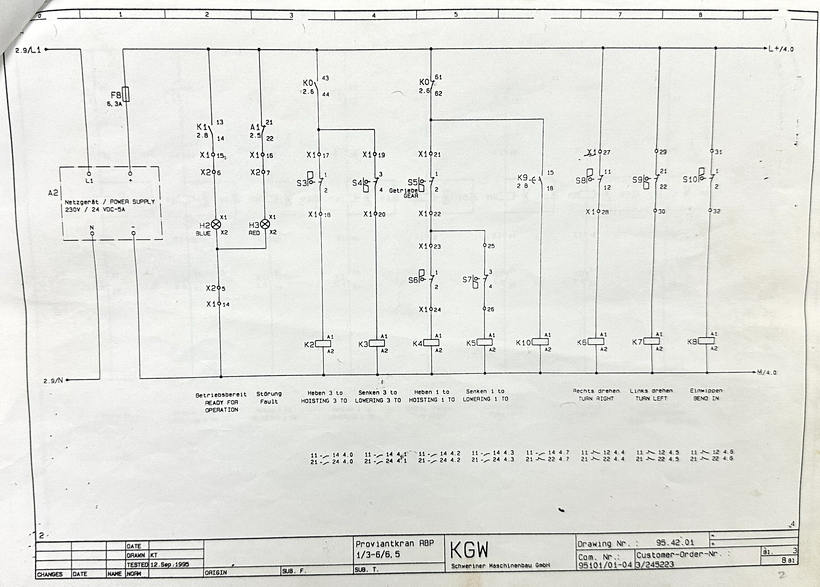
Image 05: Mechanical roller-types S3 and S6 hoisting limit switches The Modification Task
Original Configuration:
Hoisting limit switches: Mechanical roller-type (’S3’ for 3 Tons and ‘S6’ for 1 Ton)
Wiring: 2-wire (Common + N.O. contact terminals 13-14)
Logic: Contact opens when hoist reaches maximum height
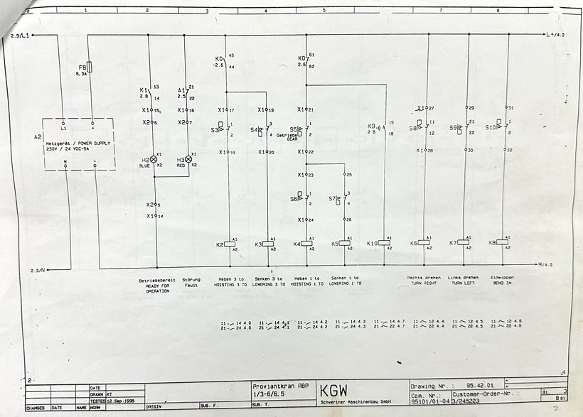
Image 05: Mechanical roller-types S3 and S6 hoisting limit switches New Configuration:
Hoisting limit switches: Inductive proximity sensors
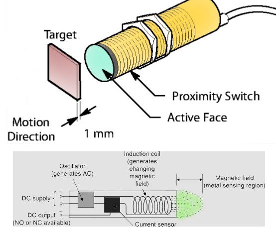
Specification: 24VDC, 3-wire (positive supply, negative/ground, signal output)
Logic: Normally energized signal (energized when limit not reached, drops to 0V at max hoist)
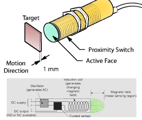
Image 06: Proximity switch principle 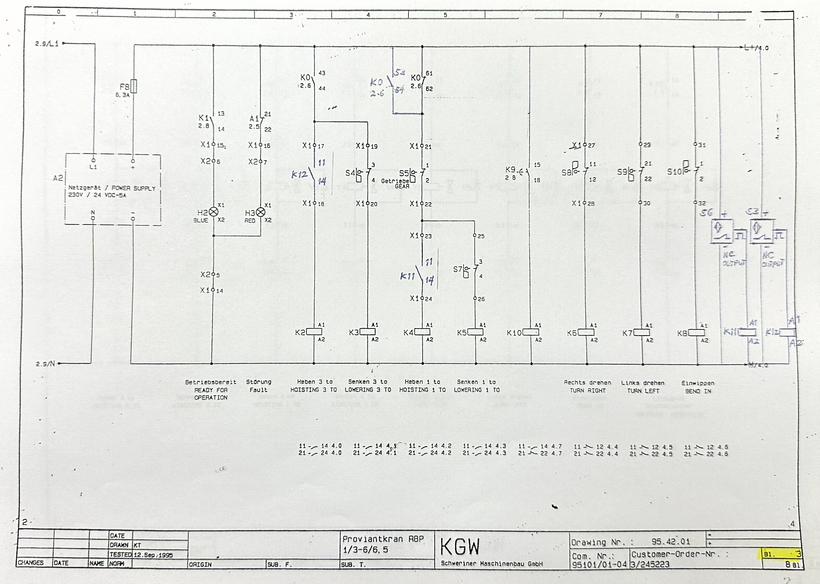
Image 07: Inductive proximity switches S3 and S6 with added auxiliary relays K12 and K11 respectively. The Challenge:
New proximity sensors output a single signal leg (the DC output, see Image 05) but the existing control logic expected dual-contact input (common + N.O.).
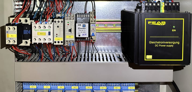
Solution: Install auxiliary relays K11 and K12 with 24V DC coils (see Image 06) to interface between the proximity sensor signals and the original control circuit design—essentially translating 3-wire sensor logic into 2-wire relay contact logic.
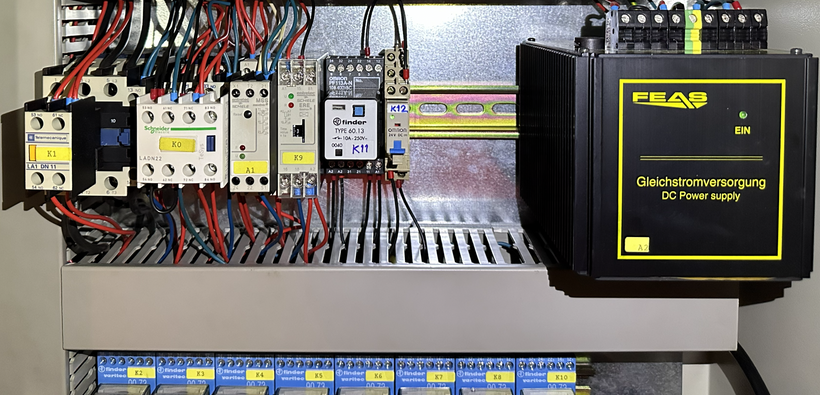
Image 08: Installed auxiliary relays K11 and K12 Execution:
Main switch Q1: OFF
Installed auxiliary relays K11 and K12 for both 1T and 3T hoist limits, respectively
Rewired control logic to accept new sensor signals
Verified all connections with insulation resistance testing
Continuity checks on all new wiring
Modification complete, control logic tested with multimeter
All measurements good
Status: Ready to restore power.
THE PROBLEM
First Energization Attempt
Closed main switch Q1 → Immediate fault → F4 and F5 both blown
Wait, what? I didn’t touch the power circuit. Just control logic modifications.
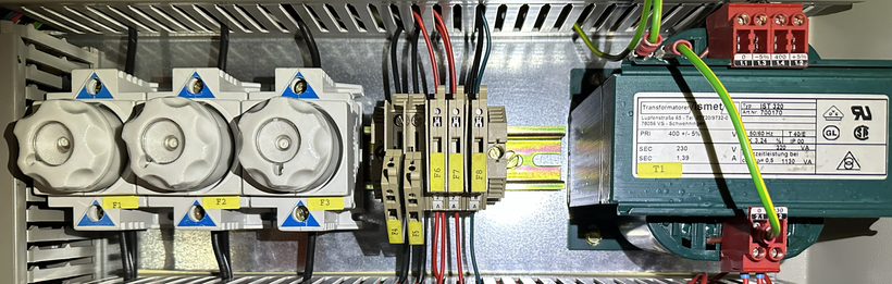
Image 09: Fuses F4-F5 blown Troubleshooting Sequence
Attempt #1: Check Secondary Circuit
Hypothesis: Did I make a wiring error creating a fault path?
Action:
· With loads connected at the secondary of transformer -T1, measured total secondary load resistance.
· Look for any low-resistance path that would indicate a short.
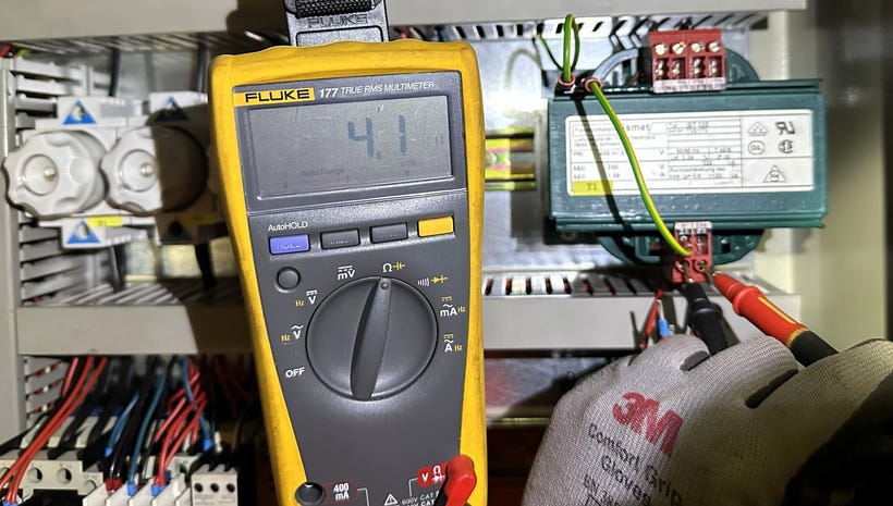
Result: Secondary load resistance: 4.1 Ω — low resistance, is it a short circuit?
Test:
· Replaced F4 and F5 with new 2A Diazed fuses.
· Closed Q1
Result: F4 blown this time
Conclusion: There is ambiguity where is the fault coming from
First doubt: “Did I wire something wrong that’s creating a fault path I can’t see?”
ATTEMPT #2: Verify My Wiring
Hypothesis: Short circuit in secondary wiring from my modifications
Action:
Isolated all secondary loads (removed F6, F7, F8 from circuit)
This disconnects all control loads, space heaters, and DC power supply
Test:
Replaced F4 with new 2A Diazed fuse.
Closed Q1
Result: F5 blown this time (alternating failures)
Conclusion: Not a secondary short circuit. If it were, isolating the loads would have solved it.
Second doubt: “Is the transformer failing? This vessel is already 28 years old, and all devices have aged...”
ATTEMPT #3: Check for Ground Fault
Hypothesis: Phase-to-phase shorted and phase-to-ground fault upstream
Action:
Measured phase-to-phase resistance at Q1 load side (all three phases)
Measured phase-to-ground resistance (each phase to earth)
Result:
All P-P measurements: OL (open circuit, MΩ range) — good
All P-G measurements: OL (open circuit, MΩ range) — good
No ground fault detected
Test:
Replaced F5 with new fuse
Closed Q1
Result: F4 blown again
Conclusion: No ground fault. System isolation is perfect.
At this point, the doubt creeps in deep. You’ve checked everything twice. My measurements are solid. But something is still wrong—and you can’t see it. That’s the worst feeling in electrical troubleshooting: when the invisible beats the methodical.
ATTEMPT #4: Transformer Health Check
Hypothesis: Transformer winding failure (internal fault)
Action:
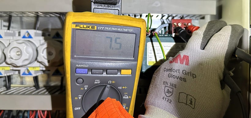
Disconnected transformer to test it in isolation
Measured primary winding resistance: 7.5Ω
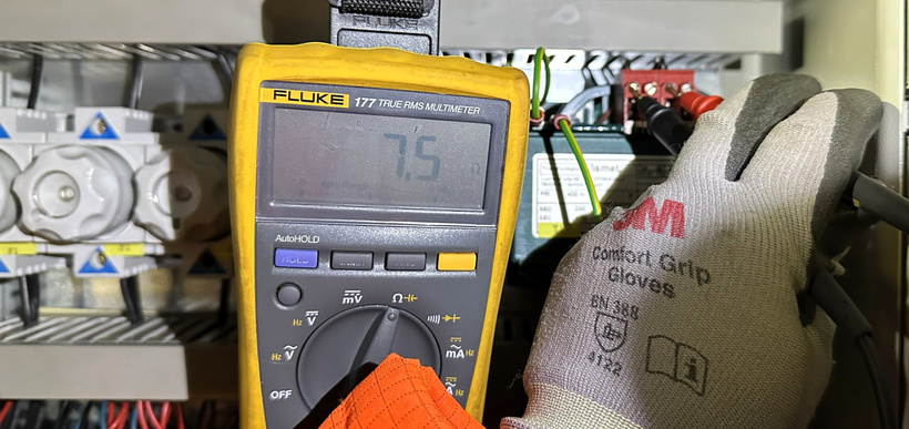
Image 10: Primary winding resistance Measured secondary winding resistance: 4.1Ω
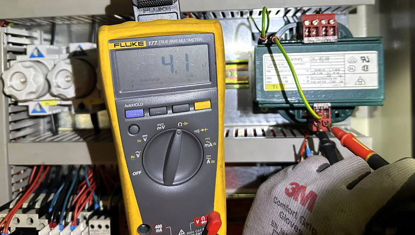
Image 11: Secondary winding resistance with loads isolated Initial reaction: “These resistances seem low—is there an internal short between windings?”
Reality check: Pulled out transformer nameplate specs:
Primary: 400V, 320VA → nominal current = 320VA/400V = 0.8A
For 0.8A at 400V, winding resistance should be low
Secondary: 230V, 1.39A → similar logic applies
320VA transformer = low impedance design by nature
Checked calculations:
Primary resistive voltage drop: I × R = 0.8A × 7.5Ω = 6V (only 1.5% of 400V)
This is completely normal for power transformers
Measured values match nameplate specifications exactly.
Conclusion: Transformer windings are healthy. Low resistance is normal, not a fault indicator.
After three failed attempts and five fuses blown (F4 ×3, F5 ×2), I was running out of ideas. Every measurement said ‘healthy system,’ but every energization said ‘BOOM.’ Then I tried something different...No fault found anywhere. What am I missing?
In the next part, we’ll dive deep on the breakthrough, the physics behind it, and lessons learned from the field.
Keep on probing!
-Lem | ProbeLem
ProbeLem is a troubleshooting library built from real shipboard electrical work, diagnostics, and field reflection.
If this post helped, follow the blog for future case studies and leave a comment with the fault, system, or lesson you want explored next.

Comments
Post a Comment