ProbeStudy No. 03: Space-Time Jutsu — The Complete Case Study
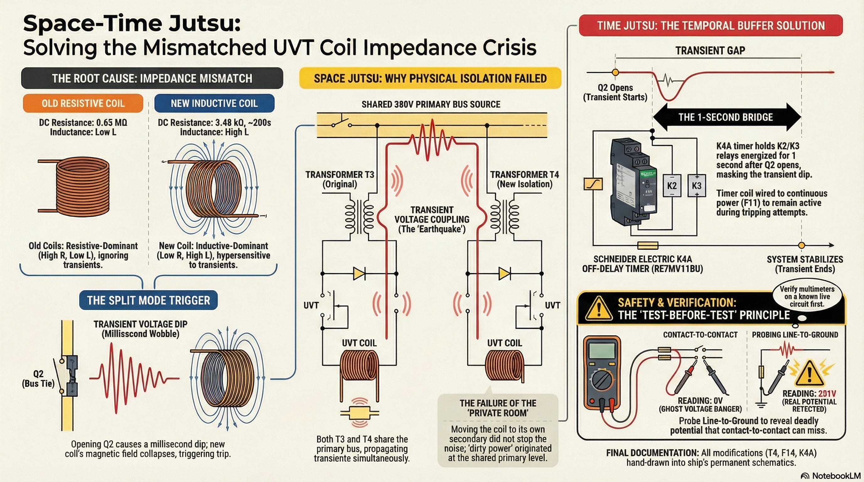
By Lem Regio | Fleet ETO | ProbeLem
“I never understood learning — until I experienced it. I never found clarity — until I taught it.”
Series Companion Piece This article is the written companion to the ProbeLem three-part YouTube docu-vlog series:
Part 1: How UVT Coil Impedance Mismatch Caused MCCB Nuisance Tripping
Part 2: How We Tried (And Failed) to Fix UVT Coil Impedance Mismatch
Part 3: MCCB Kept Tripping for 1 Year — Space-Time Jutsu Fixed It
What follows is the full engineering narrative — from problem to failed solution to final breakthrough — told exactly the way it happened. No textbook polish, no skipping the dead ends.
PART I: THE MYSTERY
Problem Identification
1.1 Twenty-Eight Years of Reliable Service
I want you to picture a machine — a massive, incredibly complex machine. A floating city. A chemical tanker ship. It has been running perfectly, day in and day out, for 28 years, which in a marine environment is an eternity. Saltwater, vibrations, temperature extremes, and the relentless operational tempo of the merchant fleet. The crew knows every single hum and rattle on this vessel. It is reliable.
And then one single component breaks. Just one. A circuit breaker. Standard stuff — it happens all the time.
The patient: The Main Switchboard (MSBD) of a 28-year-old chemical tanker. For 27 of those years, the three hydraulic power pack MCCBs operated without incident. They opened, they closed, they protected the power packs. No drama. No surprises.
Then a Fleet ETO before me performed a routine retrofit.
The original MCCB — a Merlin Gerin unit — had developed a mechanical fault. The locking mechanism had failed. Even when manually assisted to the closed position, it would not hold. After reset, it would drift back to mid-position — not fully closed, not fully open. Just stuck in limbo. The breaker was mechanically finished.
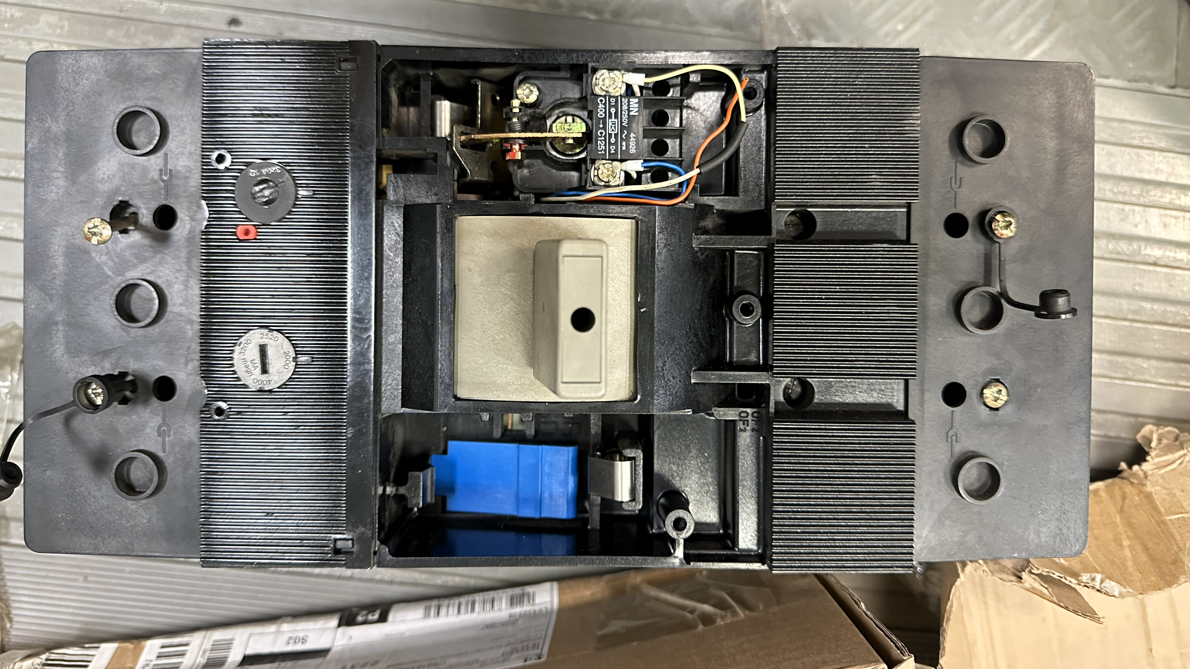
The problem was that this specific Merlin Gerin part was completely obsolete. You could not order a replacement from any catalogue on the planet. So the previous technician did the standard, correct thing: he sourced a modern equivalent. He selected a Schneider Electric NSX 400N series breaker — same voltage rating (220V AC), same frame size, same rated current. On paper, it was a straightforward like-for-like swap.

The specs matched perfectly on paper. It fit right into the same slot.
But the ship strongly disagreed. Violently disagreed, actually. Because immediately after the installation, this 28-year streak of perfection was over. And it was not just over — it was replaced by a bizarre mystery that effectively held the ship’s entire electrical system hostage for one full year.
1.2 The MSBD and Split Mode Operations
To understand where the fault occurred, we need to understand the power system.
The MSBD connects the Shaft Generator (SG), Diesel Generator 1 (DG1), and Diesel Generator 2 (DG2) to the main busbar and shaft generator busbar. The coupling switch — designated Q2 on the ship’s schematics — is the bus tie breaker that connects or separates these two busbars.
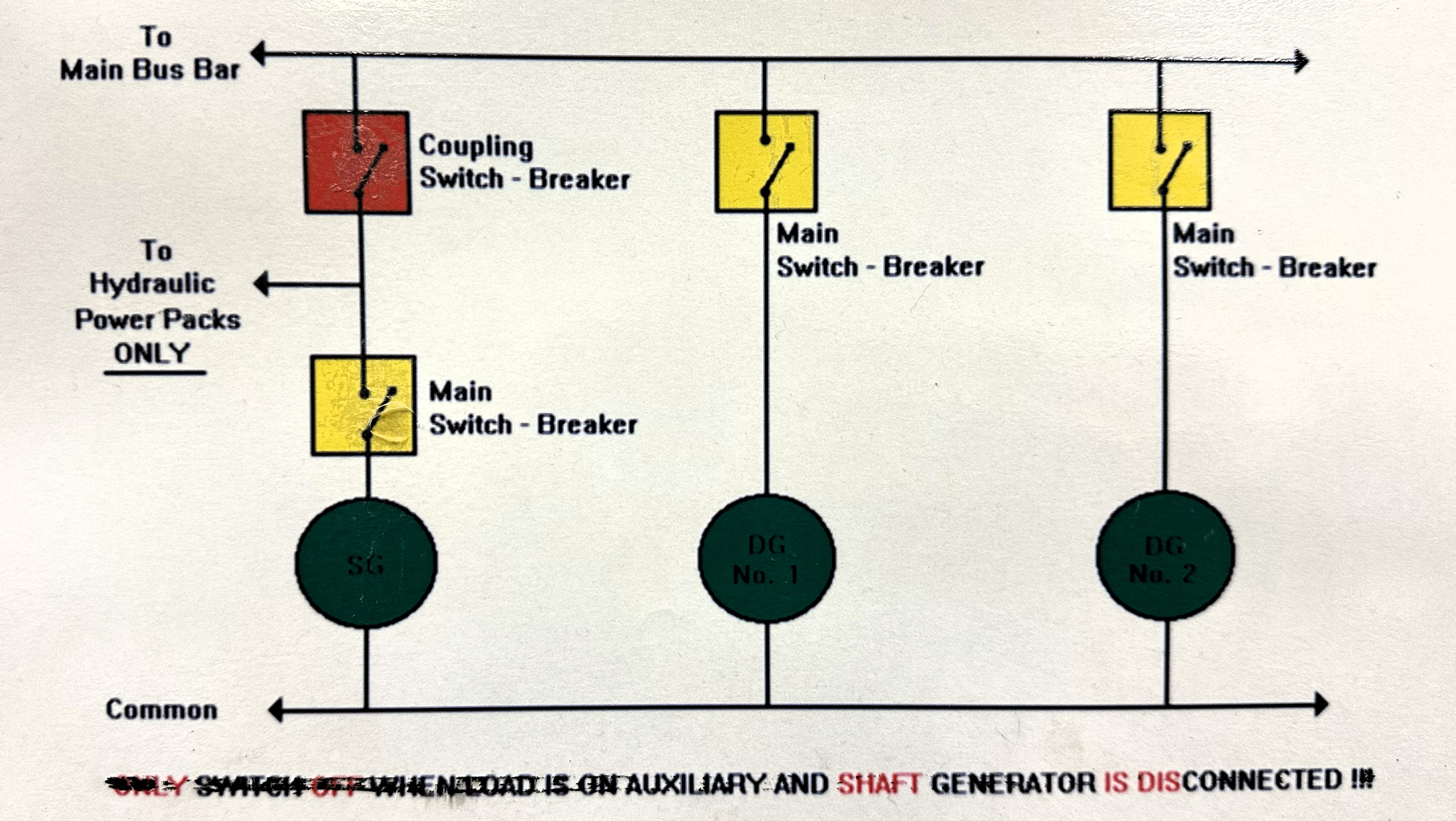
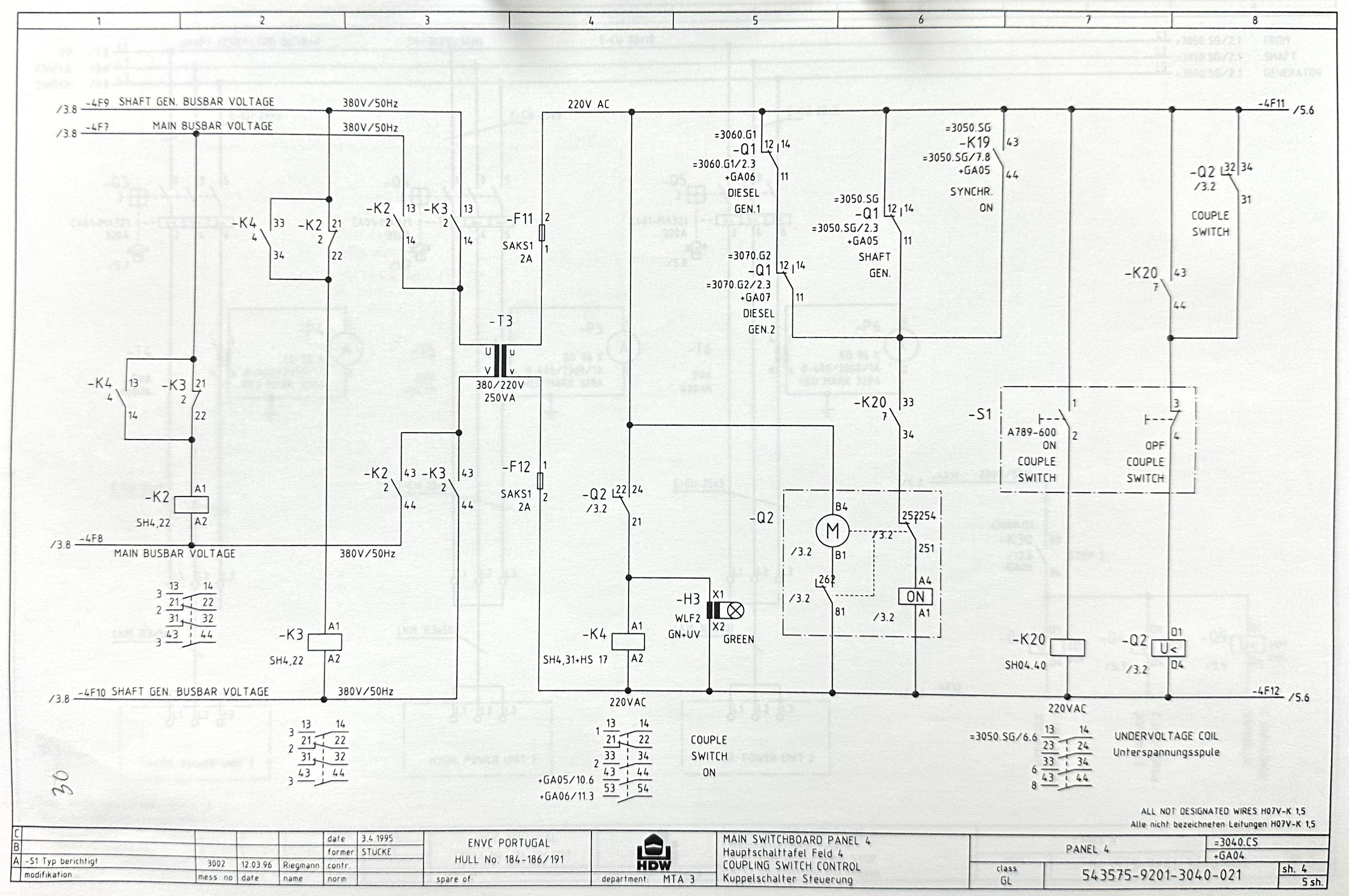
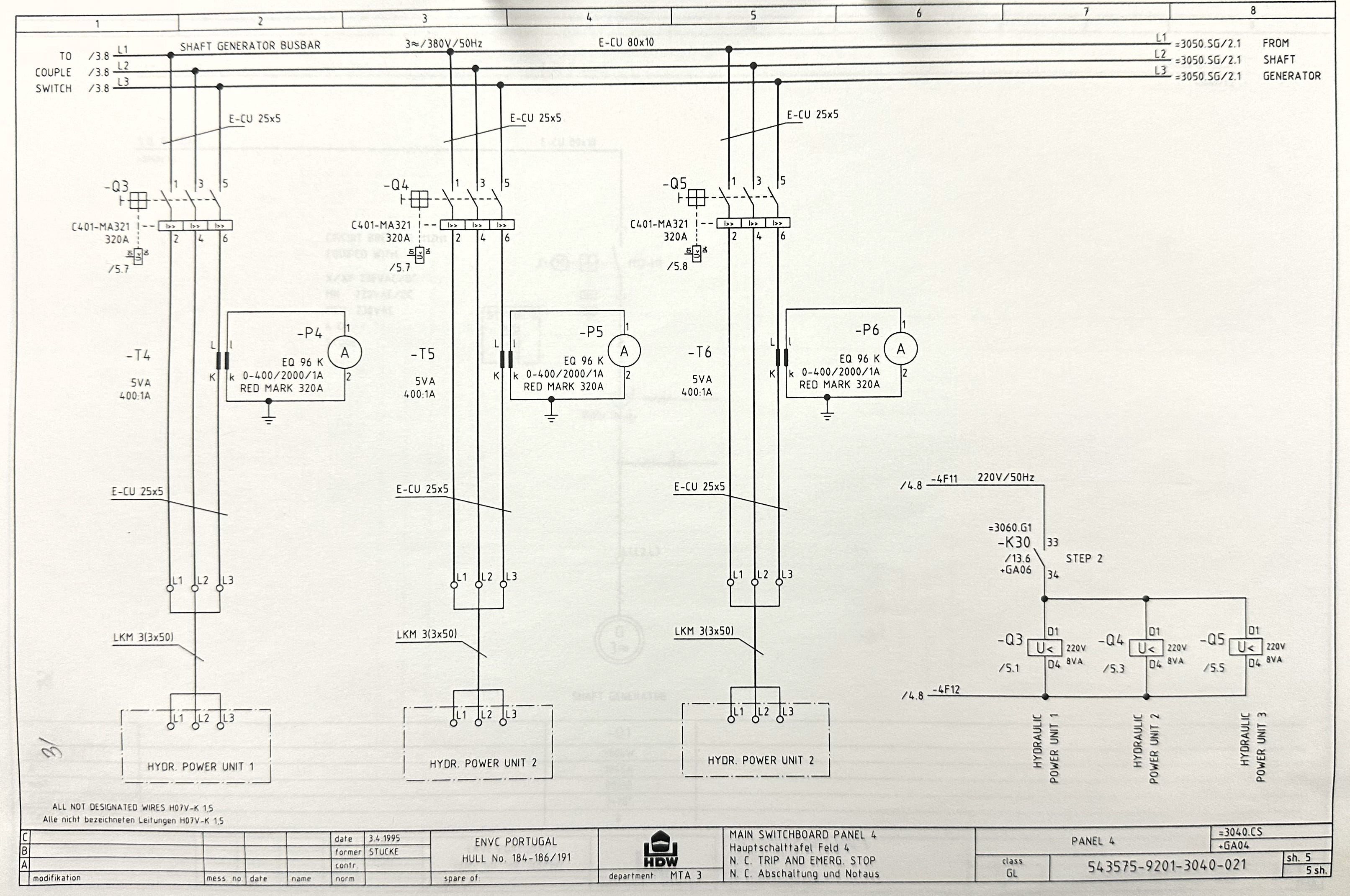
Opening Q2 is the act of entering split mode — separating the ship’s electrical grid into two independent islands. This is not some exotic, highly dangerous maneuver. It is standard operational procedure. You don’t want one fault taking down the whole ship. It is routine.
Three hydraulic power pack MCCBs sit on the busbar:
Q3 — Power Pack No. 1 (original Merlin Gerin breaker)
Q4 — Power Pack No. 2 (the new Schneider Electric replacement)
Q5 — Power Pack No. 3 (original Merlin Gerin breaker)
Every time the operator on the ECR opened Q2 to enter split mode, Q4 — and only Q4 — would panic and trip. Power Packs No. 1 and No. 3 did not even blink. The old veterans just kept working. Only the new guy freaked out.
1.3 The Symptom: Nuisance Tripping on Split Mode Entry
The specific symptom was precise and repeatable: Q4 tripped via its Undervoltage Trip (UVT) every single time the ship entered split mode by opening the coupling switch Q2.
This UVT is a protective device. It is designed to trip the breaker when the bus voltage (380V primary) affecting the secondary (230V) and drops below a threshold — typically below 207V on the IEC range (rated 220–240V). Its job is to protect the hydraulic power pack from running on inadequate voltage.
But the UVT was not responding to a real undervoltage condition. The bus voltage was not collapsing. The other two breakers — Q3 and Q5 — proved that. They were monitoring the exact same voltage and they saw nothing wrong.
The UVT on Q4 was seeing a phantom. It was triggering on something invisible to steady-state measurement — something that only existed for a fraction of a second during the switching transient.
1.4 The Second Symptom: Fuses Blowing Intermittently
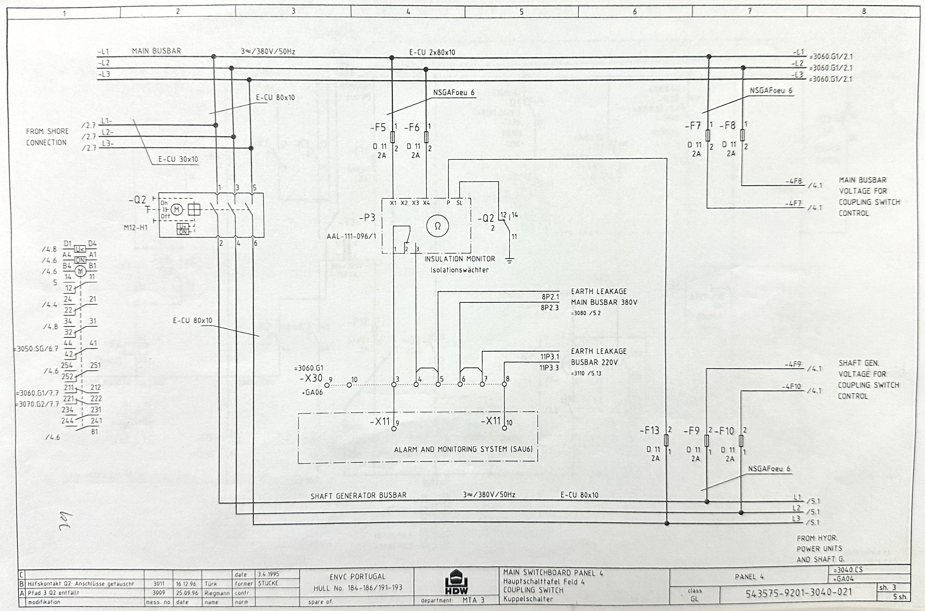
A second, seemingly unrelated problem emerged during the investigation. Control circuit fuses were blowing intermittently during the same switching event — the opening of Q2.
The MSBD control circuit is designed with a redundant 380V 50Hz AC power supply for reliability. It receives voltage from two separate sources:
Main busbar voltage through fuses F7 and F8
Shaft generator busbar voltage through fuses F9 and F10
Both sources feed downstream loads including the coupling switch Q2 control circuit and the hydraulic power pack UVT coil supply through transformer T3.
Here is where the troubleshooting got strange. We noticed a bizarre pattern:
When fuse F7 blew on one occasion, no unwanted tripping occurred during split mode operation. After F7 was replaced, unwanted tripping immediately returned.
Similarly, when F10 blew during another incident, we operated for several days without replacement and experienced zero unwanted trips. Once F10 was replaced, the tripping problem came back.
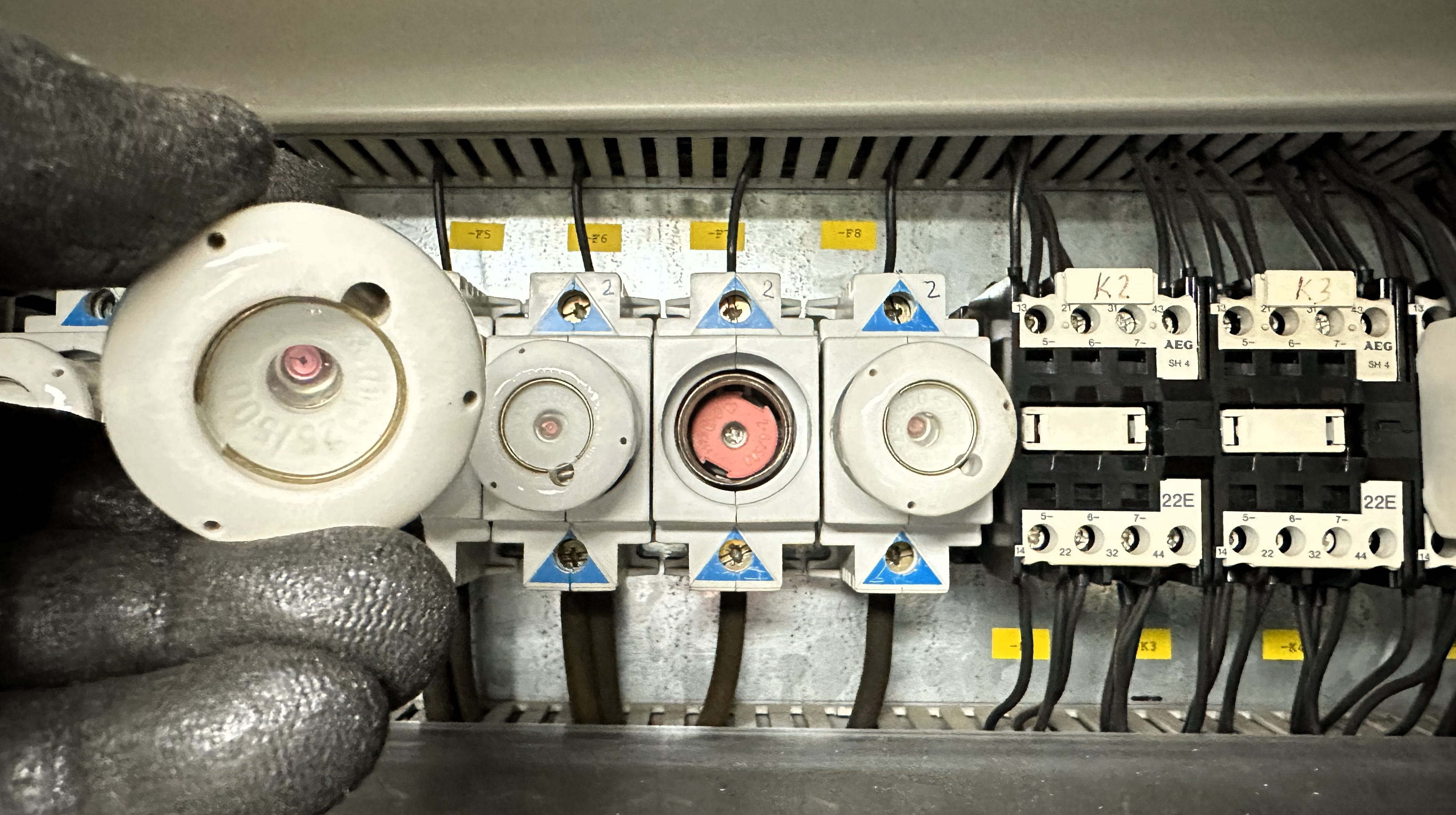
The broken state actually fixed the tripping.
This was the first major clue. This pattern suggested that the redundant power supply itself was participating in the fault. The system was designed to be more reliable by providing backup power — but here, the system was almost too connected. The redundancy was feeding the problem.
This is a classic troubleshooting nightmare: “I fixed the fuse and now the machine is broken again.”
1.5 The Breakthrough: Measuring the UVT Coils
The troubleshooting went through multiple iterations, including transformer secondary load isolation, voltage measurements under switching conditions, and detailed circuit analysis. But the real breakthrough came when we decided to compare the old breakers to the new one at the component level.
We wanted to see if this “equivalent” replacement part was actually equivalent inside the casing. The data sheet said it was. But we took a multimeter directly to the UVT coils.
Here is what the measurements revealed:
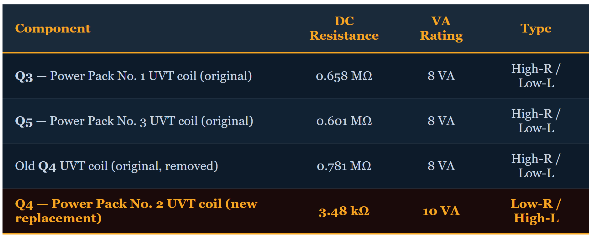
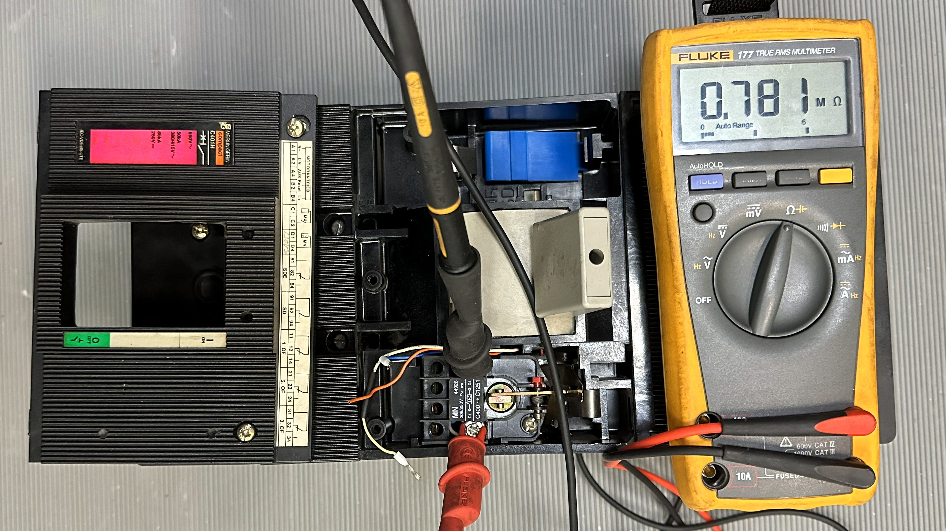
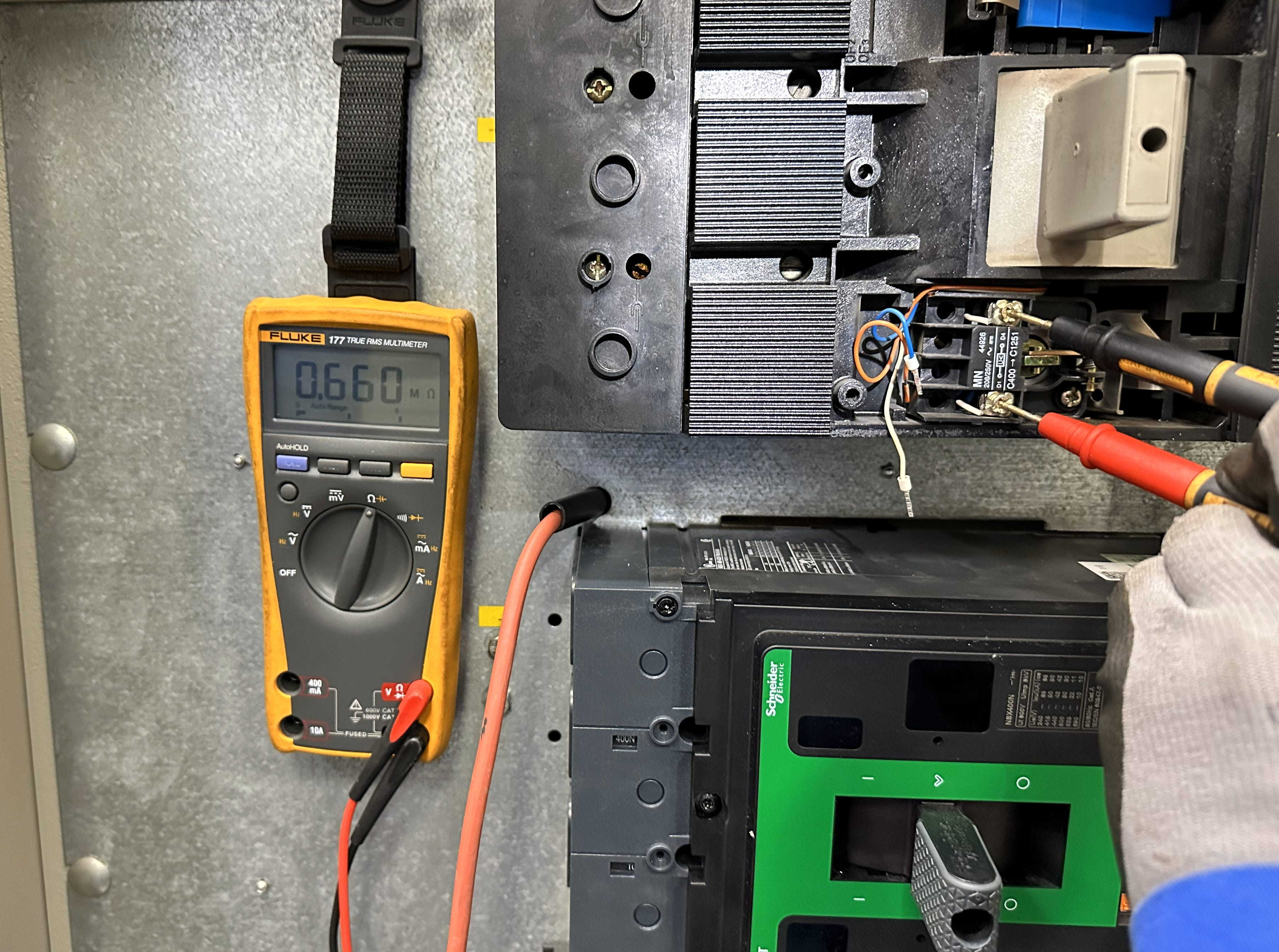
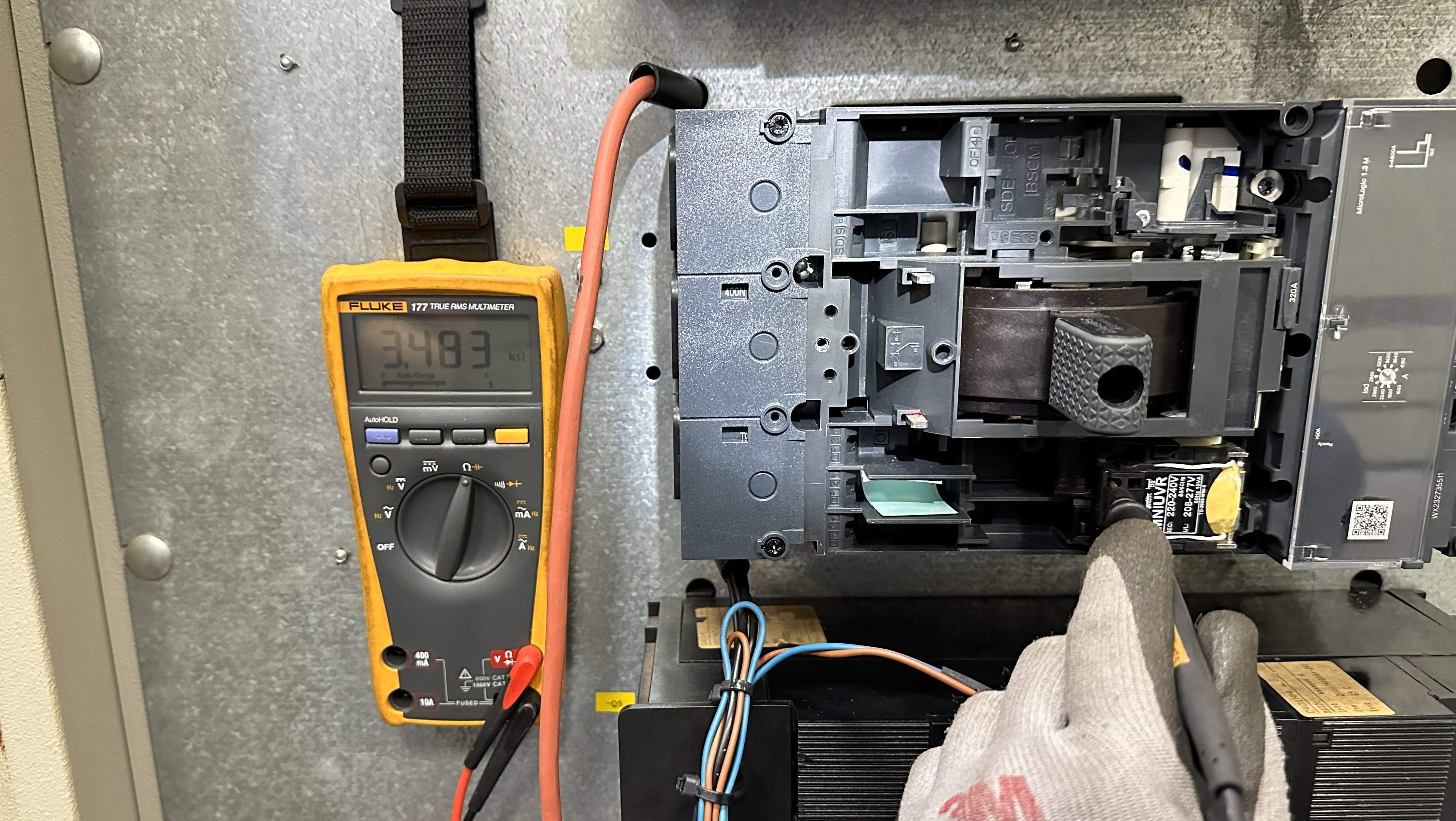
The numbers were unambiguous. The new coil had a DC resistance nearly 200 times lower than the original coils. And a higher VA rating — 10 VA versus 8 VA.
When I first saw this, I remember the exact feeling. It was the moment after a long troubleshooting session — coffee was cold, hands were cramped from holding multimeter probes inside the panel. My colleague and I stared at the display: 3.483 kΩ. Then we looked at the other readings, all hovering around 0.6–0.7 MΩ. The silence between us said everything before either of us spoke.
It was the feeling you get when the fog lifts and the landscape suddenly makes sense. Every symptom — the selective tripping, the fuse blowing pattern, the redundancy paradox — all pointed to this single measurement. The new coil was not defective. It was not installed incorrectly. It was simply, fundamentally, a different animal than the three coils it was supposed to live alongside.
Let me put the numbers in perspective: Imagine three people sharing a water pipe. Three of them have been sipping through narrow straws for 28 years. Then one of them swaps their straw for a fire hose. The water supply has not changed. But the dynamics of sharing have changed completely.
But the question remained: How on earth is that an “equivalent” part? If I bought a light bulb with 200 times less resistance than the one I just replaced, it would explode the second I turned it on. Current would just flood through it. Why is this new coil not melting down?
1.6 AC Impedance vs. DC Resistance — The Engineering Trap
That question — and its answer — is the core of this entire case study. And the answer lies in the fundamental difference between DC and AC power.
In a DC circuit, resistance is the only opposition to current flow. If you measure the coil with an ohmmeter, that resistance value tells you everything you need to predict current draw using Ohm’s Law: I = V / R.
If this were a DC circuit, you would be 100% correct — that new coil would be drawing massive, destructive current.
But the ship runs on AC. Alternating current. And in an AC circuit, resistance is only half the story. The total opposition to current is called impedance — and impedance has two components:
Z = R + jXL
Where R is resistance (what your ohmmeter measures) and XL is inductive reactance — the opposition created by the coil’s magnetic field as AC current alternates direction 50 times per second (50 Hz in our system).
Think of inductive reactance as electrical inertia. The coil creates a magnetic field. When the AC current tries to change direction, that magnetic field fights the change. It pushes back. The greater the inductance, the greater this pushback.
The key insight: The old coils and the new coil achieve the same job using completely different strategies:
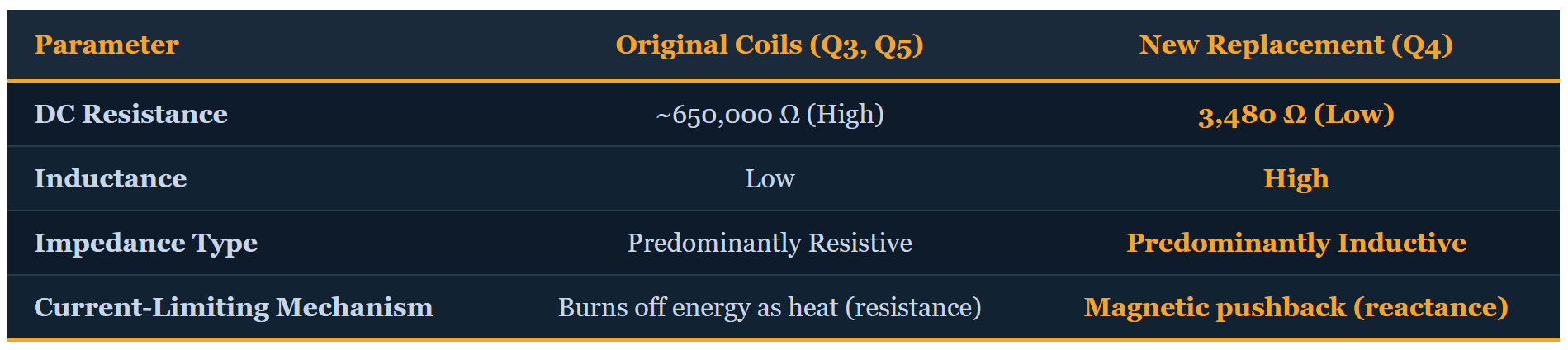
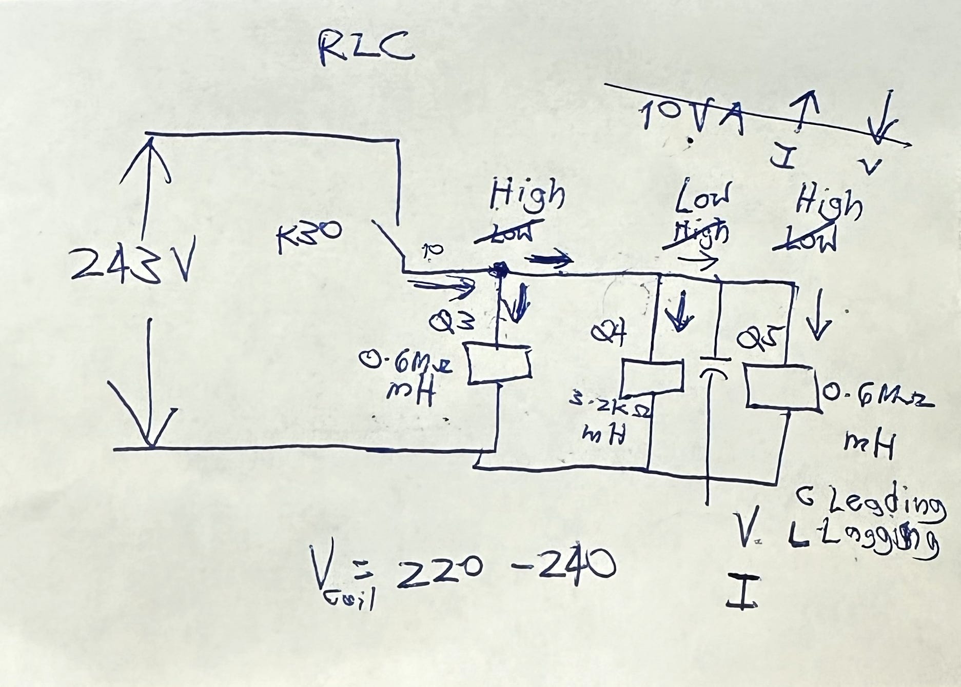
Both coils are rated for 220V AC operation. In steady state, both draw modest, manageable current:
Original 8 VA coils: I = 8 VA ÷ 220V = 36.4 mA
New 10 VA coil: I = 10 VA ÷ 220V = 45.5 mA
The steady-state current difference is modest — about 25% higher. Negligible in milliamp territory. On paper, in a steady, stable world, both coils are perfectly fine.
But the problem does not happen when they are humming along. It happens when they switch modes.
1.7 The Transient Event: When Electrical Personality Matters
Resistance is passive. It just burns off energy as heat.
Inductance is reactive. It fights change. It fights change violently.
During the split second when the operator opens the bus tie breaker Q2, there is a momentary voltage dip across the whole grid — a wobble in the power supply. All three UVT coils, connected in parallel on the secondary side of transformer T3 in a ring topology, see this wobble simultaneously.
The old high-resistance coils? They do not care. They are basically just heating elements. If the voltage dips, they get slightly cooler for a millisecond. No drama.
The new high-inductance coil? It despises change. When the voltage dips, its magnetic field suddenly collapses. That induces a back-EMF voltage, creates a current surge, and totally destabilizes its own circuit. The coil’s high inrush current demand during the transient starves the other coils of voltage — because they are all in parallel, sharing the same supply.
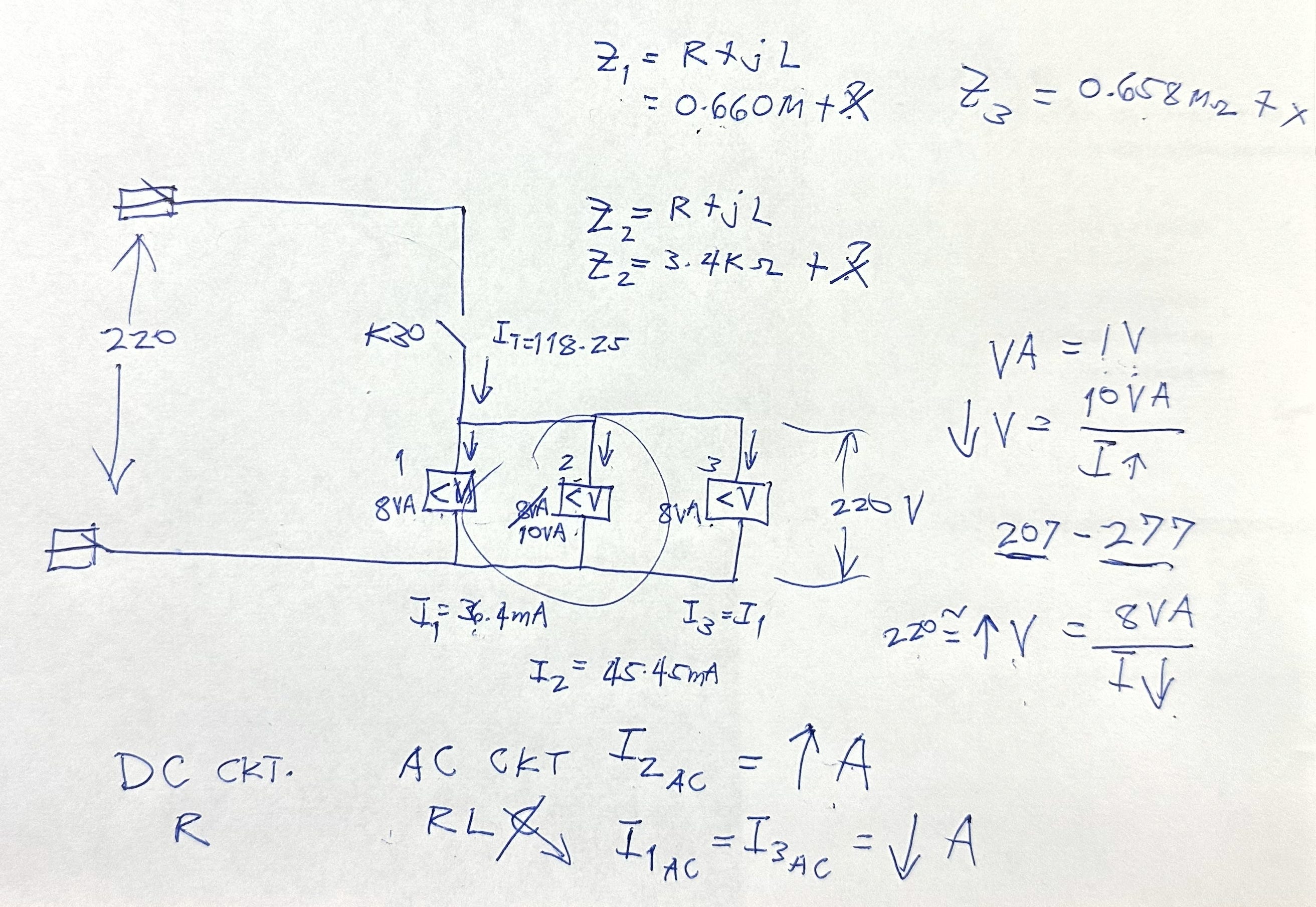
Applying Kirchhoff’s Current Law (KCL) to this parallel configuration: the total current entering the UVT coil supply node must equal the sum of currents through each branch. With one coil demanding massively more transient current, the others are starved. The voltage dips below the UVT threshold. Q4 overreacts — it sees a tiny dip, screams “power failure,” and trips the breaker.
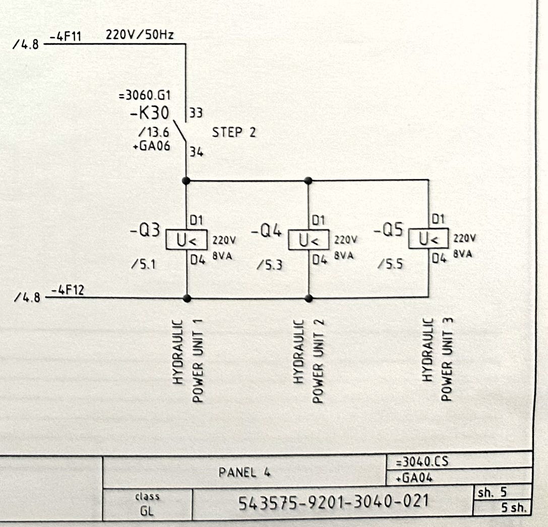
And the fuses? The violent current surges caused by Q4‘s inductive panic attacks during the switching transient — that is what blew F7/F8 and F9/F10 intermittently. When a fuse blew, it broke one leg of the redundant coupling, reducing the current path, and paradoxically stabilizing the circuit enough to stop the tripping.
The diagnosis was complete:
An “equivalent” replacement MCCB with fundamentally different UVT coil impedance characteristics — low resistance, high inductance vs. high resistance, low inductance — created a transient current imbalance in the parallel circuit during bus tie switching operations, triggering nuisance undervoltage trips on Q4 and intermittent fuse failures on the control circuit.
Now we had to fix it.
PART II: THE FAILED SOLUTION
Learning Through Failure
2.1 The Hypothesis: Physical Isolation (”Space Jutsu”)
With the impedance mismatch clearly identified, the logical first solution was physical isolation.
The reasoning was sound: If the three UVT coils were fighting because they shared a single transformer secondary (T3), then separating the mismatched coil onto its own dedicated transformer should eliminate the parallel current distribution problem entirely. Give the troublemaker its own private room, and the other two can live in peace.
We would introduce a new transformer — call it T4 — and feed Q4‘s UVT coil exclusively from T4‘s secondary. Meanwhile, Q3 and Q5 would remain happily on T3, where they had always been.
Isolate the mismatch. Separate the load paths. Clean and logical.
This is what I called “Space Jutsu” — solving the problem through spatial separation.
2.2 Safety First: Test-Before-Test and Ghost Voltages
Before any installation work began, we applied two non-negotiable safety protocols.
Test-Before-Test Principle: Before you trust any reading on a circuit you believe to be dead, you must first verify your test instrument on a known live source. This confirms your multimeter is actually working — not giving you a false zero that could convince you a live bus is safe to touch.
I checked the multimeter on a known 402V source. Confirmed. The meter was alive and accurate. Only then did we proceed.
Line-to-Ground Measurements: During the circuit work, we measured contact to contact across an open contactor. The meter read: 0 volts. Contact-to-contact. Zero. Looks dead.
But I have learned the hard way — 0 volts across an open switch does not mean the wire is safe. It means there is no potential difference between those two specific points. The wire itself may still be energized.
So I measured line to ground — from the wire straight to the ship’s metal hull.
231 volts.
The wire was hot. 231 volts to ground, meaning 380V potential between phases — all from electromagnetic and capacitive coupling with adjacent energized cables in the tightly packed switchboard. These are what we call ghost voltages. They are common on de-energized circuits in switchboards and cable runs. They will disappear if you apply a load, but they can kill you if you assume a zero contact-to-contact reading means safe.
ProbeTip: Never trust only a line-to-line measurement. Always measure line-to-ground. A zero contact-to-contact reading across an open contactor can mask a deadly 231V (or 380V phase-to-phase) backfeed through electromagnetic induction. This is not an extra step. This is the step that keeps you alive.
2.3 Understanding the Relay Logic: K2, K3, K4
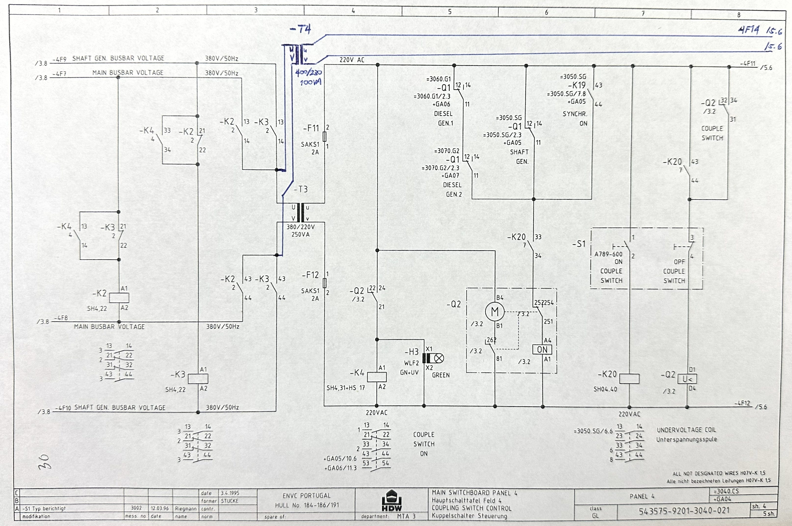
Before I describe the installation, you need to understand the relay architecture that controls the power supply to the UVT coils.
Central to the circuit are three AEG relays and transformer T3:
K2 — Main busbar voltage relay. When energized, its normally open contacts close to supply T3 primary from the main bus.
K3 — Shaft generator busbar voltage relay. When energized, its contacts close to supply T3 primary from the shaft generator bus.
K4 — Coupling switch auxiliary relay. Energized when the coupling switch Q2 is closed (busbars connected).
When Q2 is closed (normal parallel operation), both K2 and K3 are energized, providing the redundant primary supply to T3. When Q2 opens (split mode), the auxiliary contacts that energize K2 and K3 open momentarily. Both relays de-energize. For a split second, T3 loses its primary supply. The 220V secondary drops. The UVT coils see it.
Q3 and Q5 (high resistance, low inductance) tolerate it. Q4 (low resistance, high inductance) does not.
2.4 Installing Transformer T4
We could not troubleshoot live electrical systems underway. Not safely, not responsibly. So we waited for an anchorage opportunity — our window to work.
The plan:
Install a new transformer T4 (ST 0.1, 100VA, 400/230V) in the MSBD panel
Feed T4‘s primary from the same 380V bus, protected by a new fuse designated F14 (later upgraded to a Mitsubishi 2-pole MCB)
Route T4‘s secondary exclusively to Q4‘s UVT coil
Include K30 auxiliary contacts (terminals 83/84) in the supply path for preferential tripping protection
Leave Q3 and Q5 on the original T3 circuit
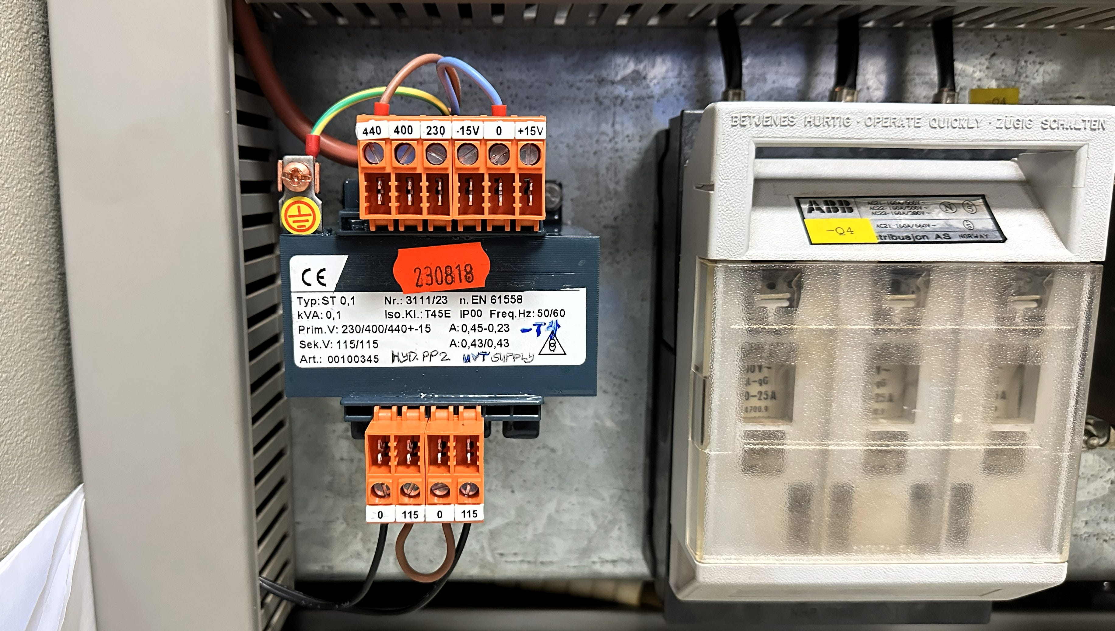
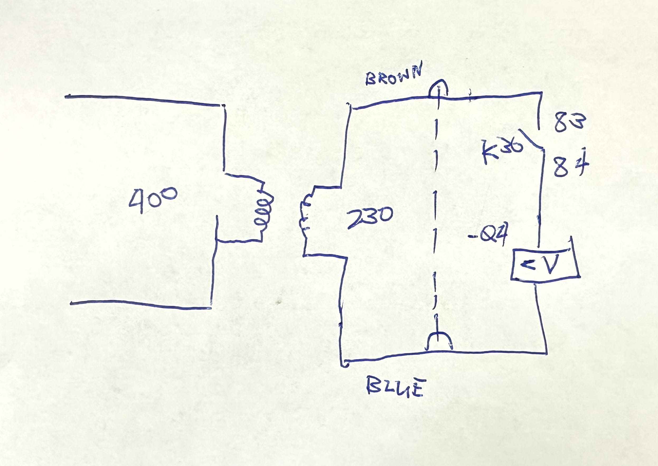
This was not just flipping a switch. This was hauling a physical transformer into the switchboard room, mounting it, running new heavy-duty cabling through the panel, terminating connections, verifying continuity, and commissioning a brand-new supply circuit inside a 28-year-old switchboard.
Hours of real physical work. Cable routing from Panel 4 to Panel 6, through overhead cable trays, down to the K30 relay, and across to the Q4 UVT coil terminals.
2.5 A Digression: The Polarity Reversal
During the circuit verification — before we even tested the T4 solution — we discovered something unexpected. The connection to the No. 2 UVT coil was reversed. The brown wire was connected to D2 instead of D1, and the blue wire to D1 instead of D2. The polarity had been swapped at some point.
Now, does polarity matter on a passive AC load? Technically, no — not in steady state. An AC coil does not care which direction the current enters during normal operation.
But when you are chasing transient voltage issues in a 28-year-old system, you leave no stone unturned. So we corrected the polarity. Reversed it back to the correct D1/D2 orientation. Verified continuity.
This is how real troubleshooting works. Not perfect. Not linear. But methodical. When new evidence emerges, you adapt. You iterate. You test. That is what separates troubleshooting from guesswork.
2.6 A Side Experiment: The Capacitor Attempt
Before committing fully to the T4 approach, we briefly explored another idea — could a capacitor compensate for the inductive coil’s voltage lag? The theory: place a capacitor across Q4‘s UVT coil to provide reactive power compensation, essentially buffering the voltage dip with stored energy.
We found capacitors onboard — one measuring 2.57 µF, another 4.05 µF — and tried connecting them across the Q4 coil terminals. The results were not encouraging. During the split mode test, sparking occurred at the capacitor terminals. The capacitor’s stored energy was nowhere near sufficient to compensate for the transient, and the physical arcing confirmed this was not a viable approach. We removed the capacitors immediately.
This was another dead end — but a useful one. It further confirmed that the problem was not about steady-state power factor correction. It was about the speed and violence of the transient event itself. No passive component sitting across the coil could absorb what was happening upstream during the switching moment.
2.7 The Moment of Truth — And Failure
With T4 installed, wired, verified, and commissioned, we prepared for the real test.
Confidence was high. We had isolated the component. We had given the mismatched coil its own private transformer secondary. The parallel impedance problem should be eliminated.
We prepared for split mode. The operator opened the coupling switch Q2.
Click. Darkness on Panel 2.
Q4 tripped again.
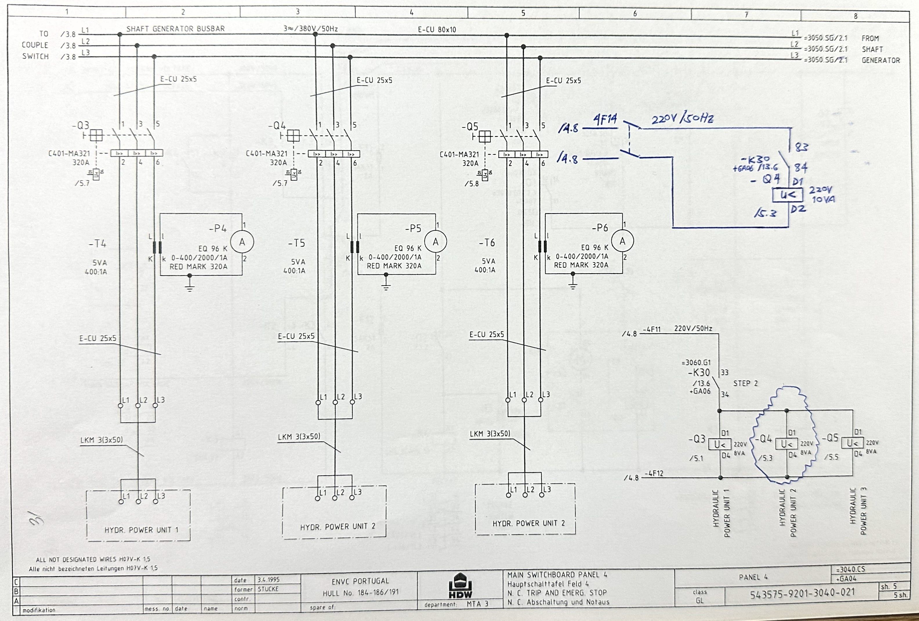
The devastation was real. All that physical work — the transformer, the cabling, the fuse, the wiring, the hours at anchorage — and it just completely failed. That sinking feeling when you have exhausted your best theory and the machine disagrees with your logic.
2.7 Why Space Jutsu Alone Failed
The reason was devastatingly simple once we understood it:
Both transformers — the old T3 and the new T4 — were fed from the exact same 380V primary source.
When the bus tie breaker opened, the transient voltage disturbance did not originate at the transformer secondary. It originated upstream, on the 380V main bus. The wobble traveled down the wires into T3 and into T4 at the exact same millisecond.
Physical separation did not matter at all — because both transformers were standing on the same shaking ground.
We had addressed the parallel secondary mismatch, but not the root mechanism: the transient voltage propagating through the common 380V primary source during split mode.
We verified this by temporarily supplying Q4‘s UVT coil from a completely independent 220V outlet — a power socket with no connection whatsoever to the MSBD control circuit. With this truly independent supply, we entered split mode.
No trip. Not once.
This confirmed our analysis: the problem was not the parallel secondary mismatch (though that contributed to the severity). The problem was the transient coupling through the shared primary source. No amount of spatial separation within the same primary bus could fix it.
We needed something else entirely.
💡 Want to follow the full ProbeLem journey? This case study is just one probe. More real-world marine electrical troubleshooting, circuit analysis, and Fleet ETO field notes are coming — subscribe so you never miss a ProbeStudy.
🎥 Prefer video? Watch the complete trilogy on YouTube:
Part 1: Problem Identification | Part 2: Failed Solution | Part 3: Space-Time Jutsu
📘 Want the full PDF with 20+ engine room photos, KCL equations, and hand-drawn schematics? Get the ProbeStudy No. 03 Mini eBook on Patreon →
The takeaway: Troubleshooting is not about forcing one solution. It is about following the evidence wherever it leads. We started with a plan — isolate the mismatched coil, separate the load paths. Logical. Methodical. But incomplete. The failure was not wasted — it was educational. It eliminated one variable and pointed us toward the real solution.
Space alone was not enough. We needed to think in another dimension.
PART III: THE BREAKTHROUGH
Space-Time Jutsu
3.1 If You Cannot Move the Component Away in Space, Move the Problem in Time
After the T4 installation failed to stop the tripping, I sat with a cup of coffee and re-examined the evidence.
The facts were now clear:
The trip happens instantaneously — within a fraction of a second after Q2 opens
The transient originates on the 380V primary bus and couples through to any transformer connected to it
An independent 220V supply (completely disconnected from the MSBD bus) eliminates the trip entirely
The voltage recovers within roughly one second — the grid stabilizes into its new configuration
Point four was the insight that changed everything.
The transient is not permanent. It is a brief disturbance — a wobble that lasts for a fraction of a second while the electrical grid transitions from parallel mode to split mode. After that fraction of a second, the voltage stabilizes. The new coil would be perfectly happy if it simply did not have to witness that one violent moment.
If we could make the coil ignore that one specific fraction of a second, everything would be fine.
If you cannot move the component away from the problem in space, you must move the problem in time.
We needed a temporal buffer.
This was the moment I named it: Space-Time Jutsu. The T4 transformer was the Space component — still necessary to separate the secondary impedance loads. The temporal buffer would be the Time component — the missing piece that would complete the solution.
Neither alone would be sufficient. Both together — Space + Time — would solve it.
3.2 The Off-Delay Timer Concept
The mechanism of the trip, restated precisely:
When Q2 opens during split mode entry, the auxiliary contacts that energize K2 and K3 open. Both relays de-energize simultaneously. Their normally open contacts open, cutting the 380V primary supply to T3 (and now also T4). For a split second — less than one second — the transformers lose primary voltage. The 220V secondary dips. The inductive UVT coil on Q4 reacts violently to this dip and trips the breaker.
The solution: delay the de-energization of K2.
If, instead of K2 dropping out instantly when Q2 opens, we force K2 to stay energized for exactly one second longer, then:
Q2 opens → K3 de-energizes immediately (shaft generator supply path disconnects)
K2 remains energized for 1 second (main bus supply path stays connected)
T3 (and T4) retain primary supply through K2 for that 1 second
The UVT coils see stable 220V throughout the transition
After 1 second, K2 de-energizes normally — but by now the grid has stabilized
The voltage is steady. No dip. No trip.
One second. That is all we needed — just enough time for the ship’s electrical grid to settle into its new configuration. By the time the timer lets go, the transient is completely over. The water is calm again.
The hardware: an off-delay timer relay.
3.3 Timer Selection: Schneider Electric RE7MV11BU
We screened the available timer relays on board and found a suitable unit after evaluating three candidates:
Selected model: Schneider Electric RE7MV11BU
Rated: 110–240V, 50/60Hz — compatible with the control circuit supply
Function: Off-delay timing
Range: 0.05s to 300s — we would set it to 1 second
Switching logic: Terminals Y1 and Z2 (C2) for the output contacts
Coil supply: Terminals A1 and A2
Timer contacts: Terminals 15 (normally open) and 18
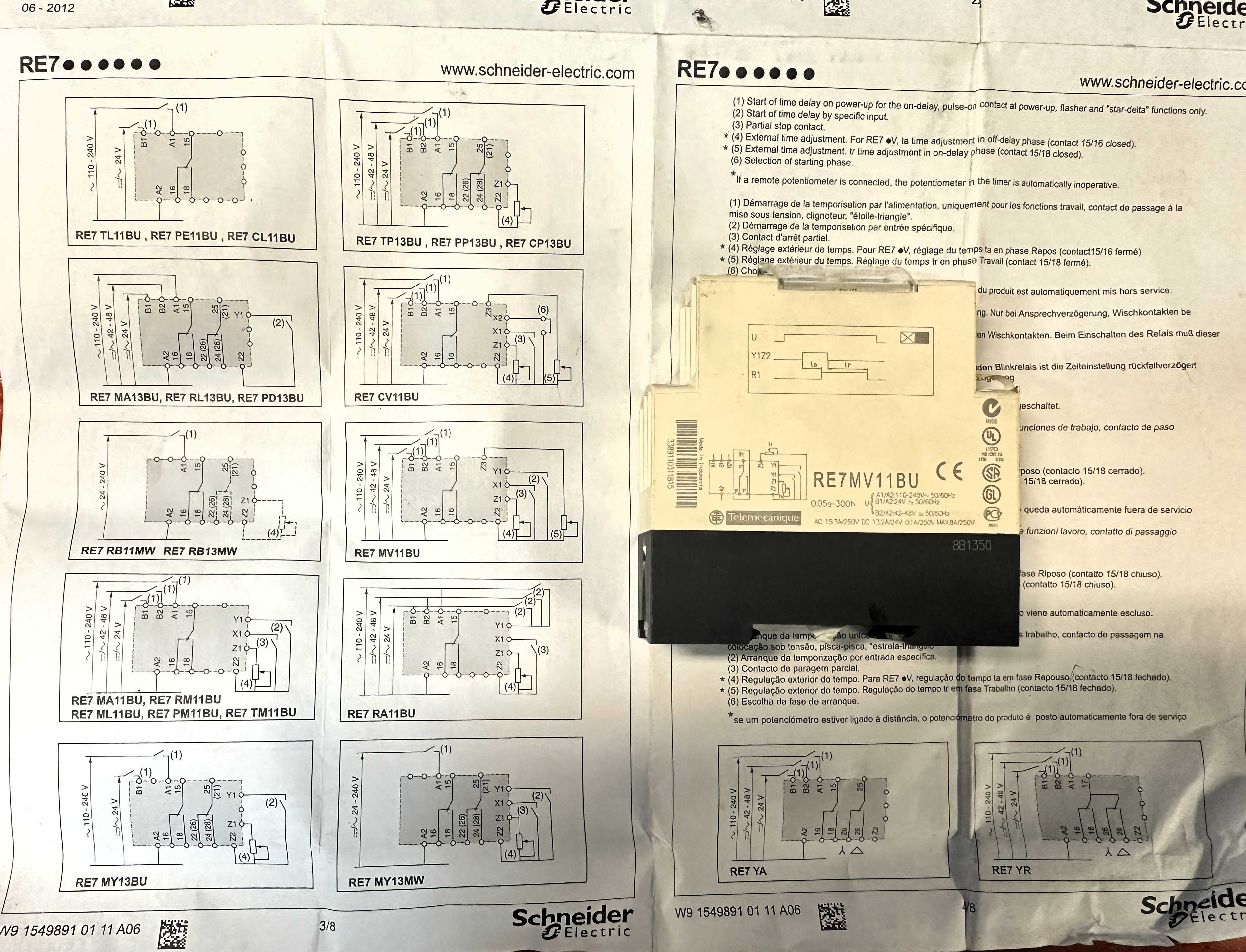
Fig. 3-1 — Schneider Electric RE7MV11BU with wiring datasheet
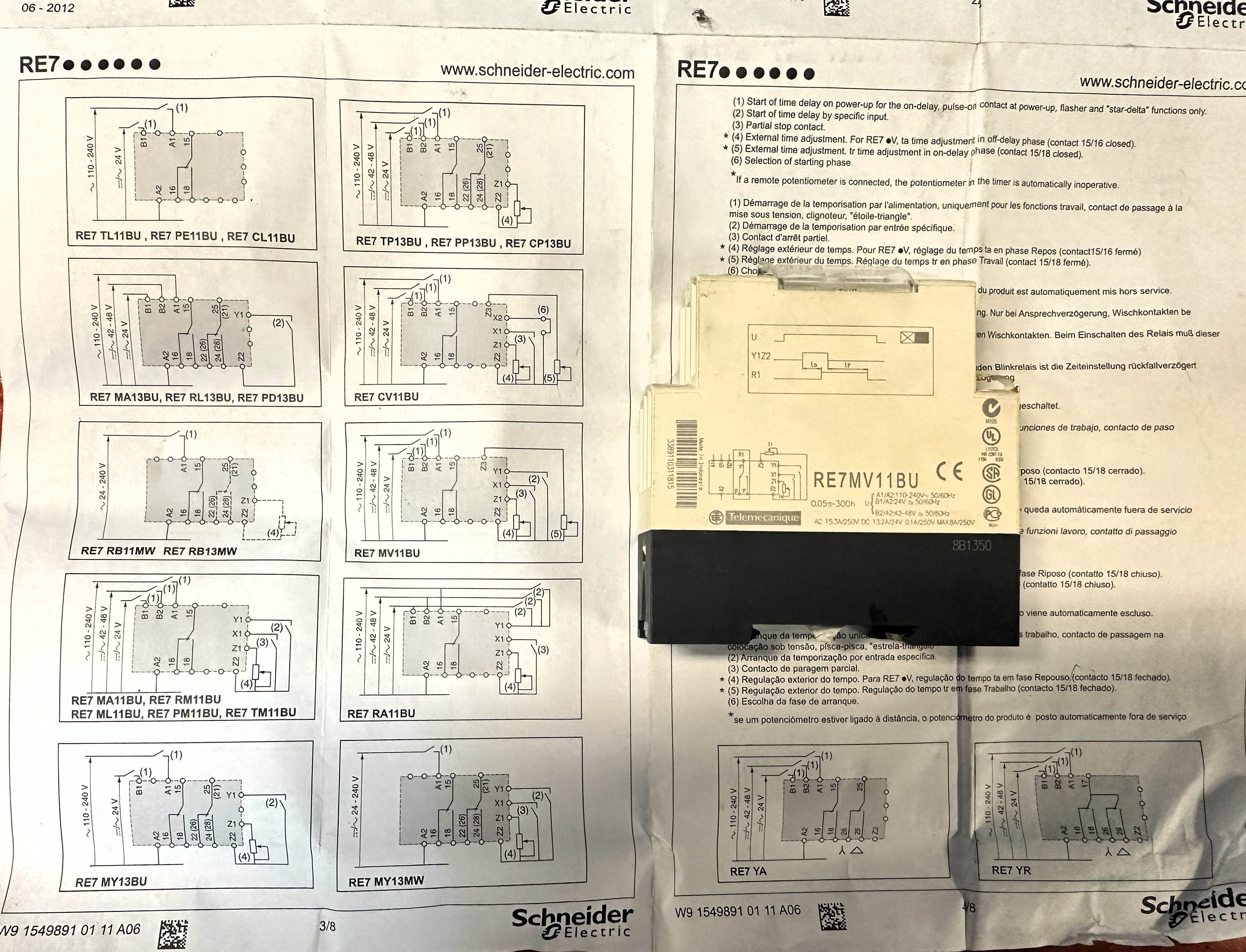
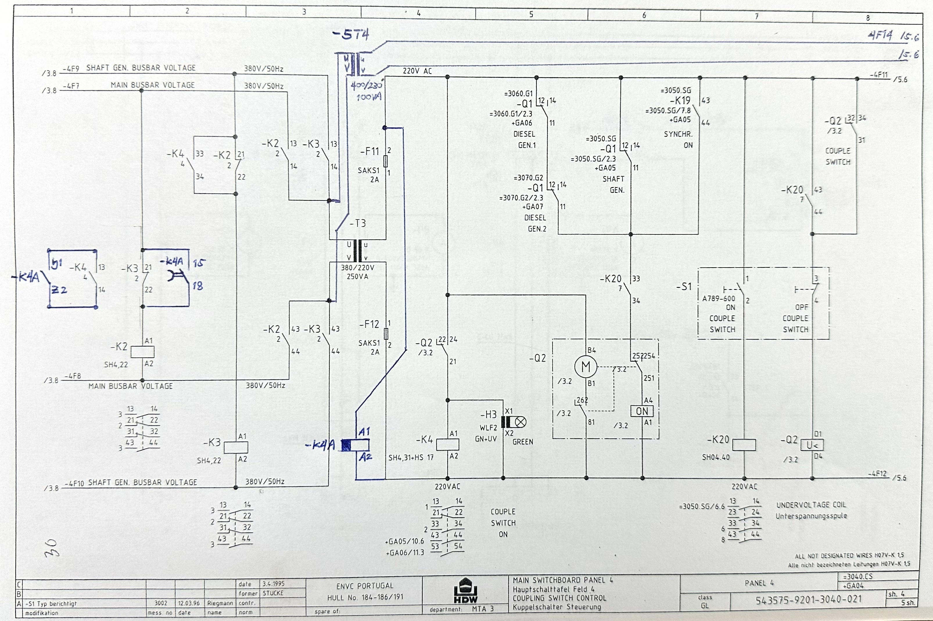
The timer was designated K4A on the ship’s circuit — the “A” suffix indicating it was an addition to the existing K4 relay function.
Configuration:
Switching logic: Switch mode (not momentary)
Time multiplier: 100% of dial setting
Time dial: 1 second
Operating mode: Off-delay — contacts remain closed while the coil is energized, and when the coil de-energizes, contacts hold for the set delay time before opening
3.4 The Circuit Logic
Here is the complete Space-Time Jutsu circuit logic:
Normal operation (Q2 closed, busbars connected):
K4 energized via Q2 auxiliary contact
K4A coil energized → timer running, contacts 15/18 closed
K2 energized through K4A contacts → main bus supplies T3 and T4 primaries
K3 energized through its own path → shaft generator supplies T3 primary (redundant)
All UVT coils see stable 220V on T3 secondary
Q4 UVT coil also sees stable 220V on T4 secondary (isolated)
Split mode entry (Q2 opens):
Q2 opens → K4 auxiliary contacts de-energize
K3 de-energizes immediately → shaft generator supply path disconnects
K4A timer begins its 1-second off-delay countdown
K2 remains energized for 1 second via K4A contacts 15/18
T3 and T4 retain primary supply through K2 for 1 full second
UVT coils see stable, uninterrupted 220V throughout the transition
After 1 second: K4A contacts open → K2 de-energizes
By now, the grid has fully stabilized into split mode — no transient, no dip
Q4 stays closed. No trip. Problem solved.
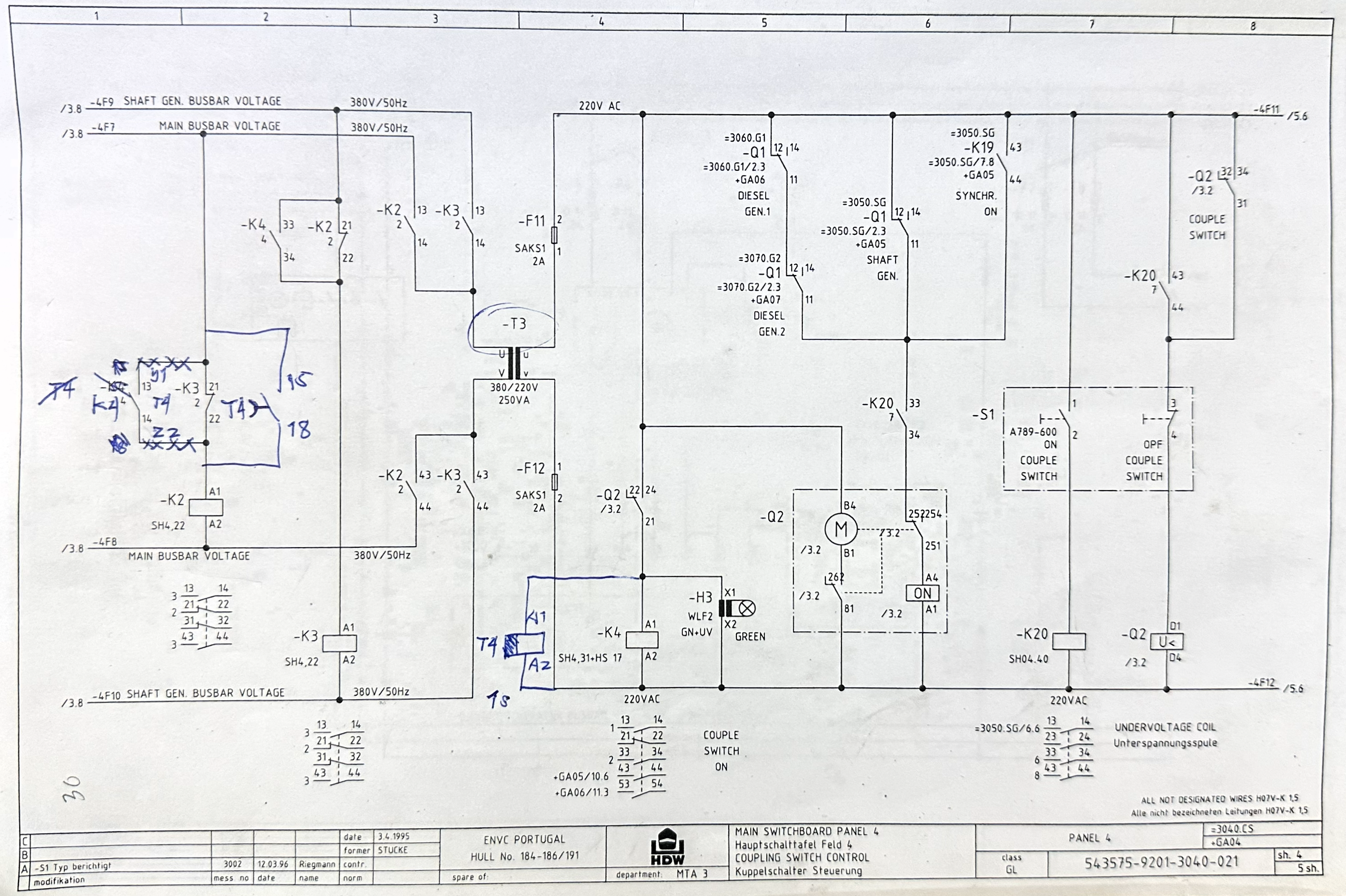
Fig. 3-2 — Draft circuit drawing for Space-Time Jutsu 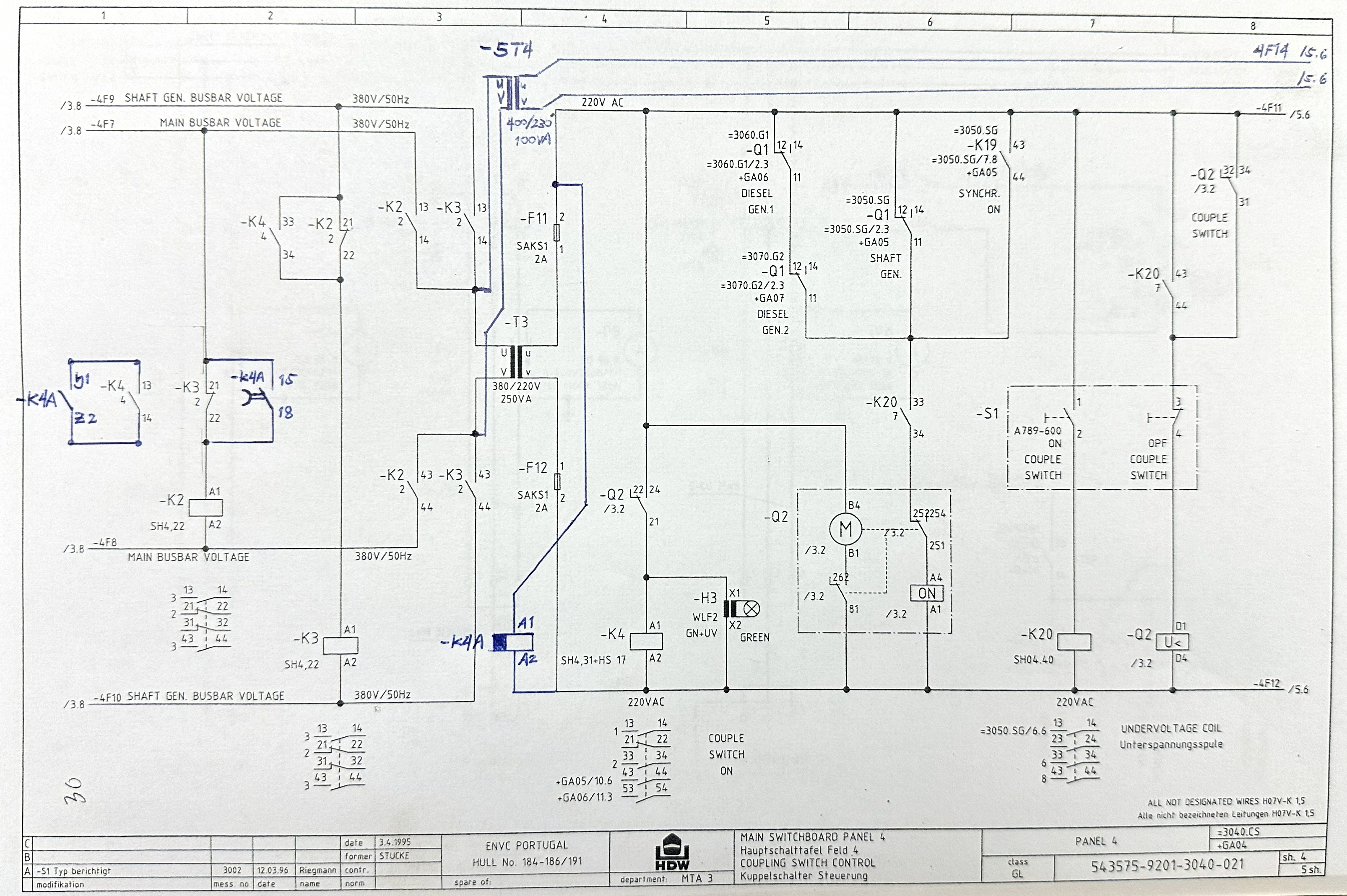
Fig. 3-3 — Final circuit drawing showing complete K4A integration
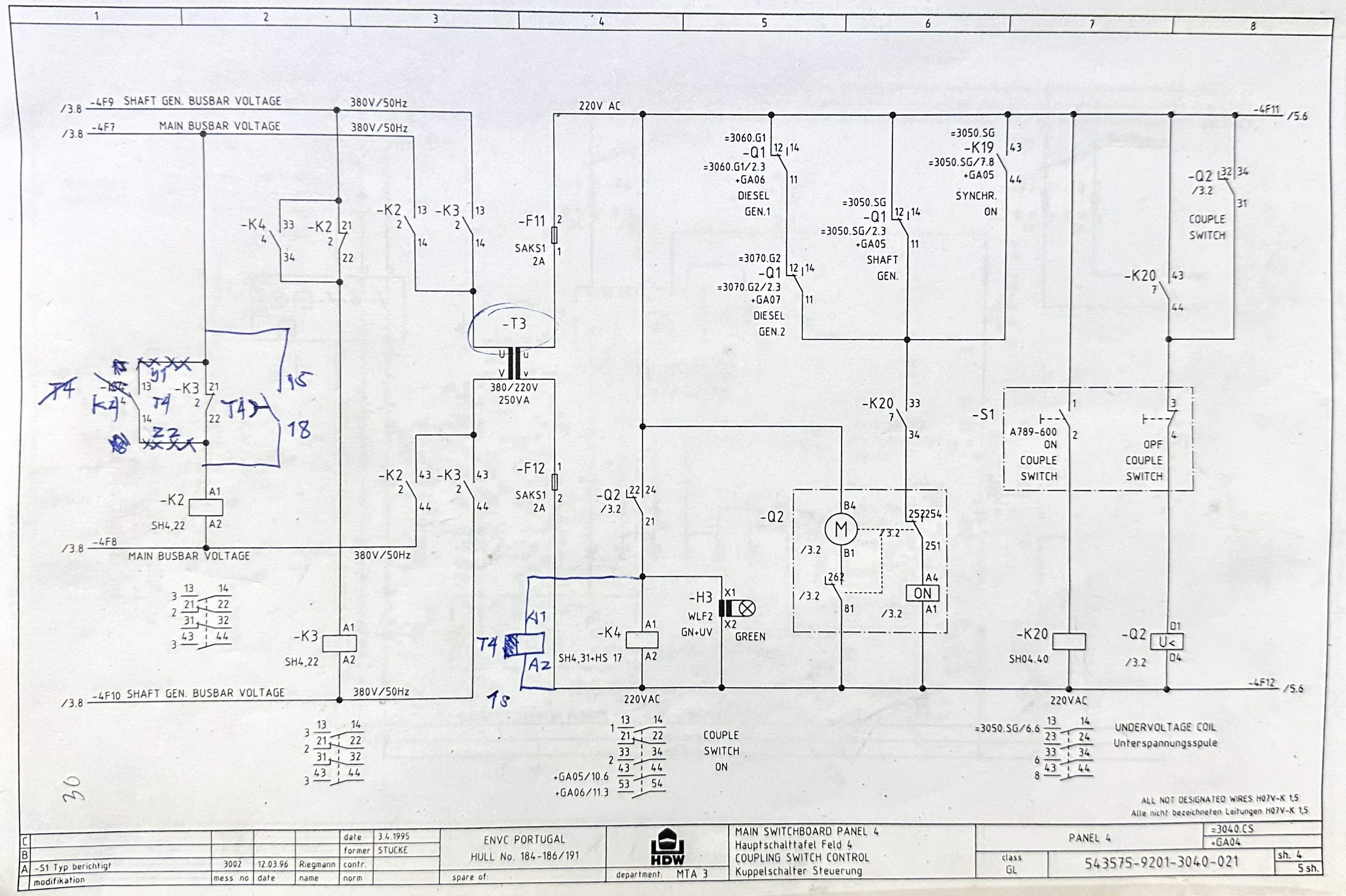
3.5 The Chicken-and-Egg Problem: Timer Power Supply
During the first wiring iteration, we made a critical mistake — one that contains an important lesson.
We initially wired the K4A timer’s coil power (A1) through Q2‘s auxiliary contact. The logic seemed correct: the timer should be energized when Q2 is closed, and begin its off-delay countdown when Q2 opens.
But here was the problem:
When Q2 opens, it cuts power to the K4A coil. The timer loses its supply. A dead timer cannot count down. The off-delay function requires the timer to be alive during the delay period — it needs to be powered while it is counting.
This was a paradox: The timer needs to be alive to save the breaker, but the breaker event kills the timer before it can even start counting. We had built a logical short circuit.
The moment we tested it, the timer lost power instantly. No countdown. No delay. No protection.
The fix: We rewired K4A‘s coil supply (A1) directly to Fuse F11 — an independent, continuously energized source that bypasses the Q2 auxiliary contact entirely.
Now, K4A remains energized at all times, regardless of Q2‘s state. When Q2 opens and K4 de-energizes, the K4A timer — still alive on its independent supply — begins its 1-second off-delay countdown. K2 stays energized through K4A‘s contacts. The bridge is held open for exactly 1 second.
Lesson: You can have the perfect theory, but if you wire it wrong, physics still wins. Execution is everything.
3.6 Physical Installation
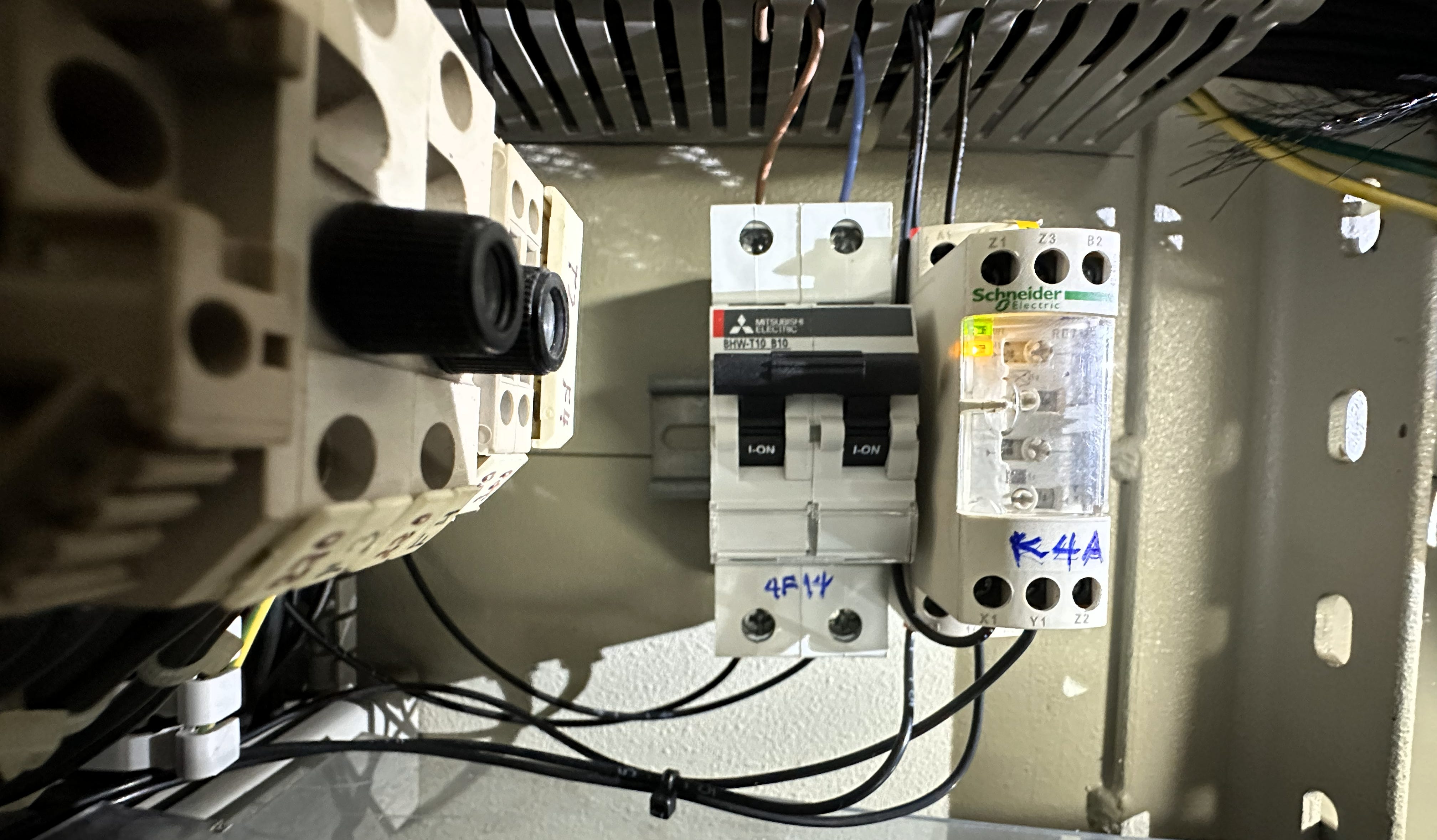
With the wiring logic confirmed, we installed:
K4A (RE7MV11BU off-delay timer) mounted on DIN rail inside the MSBD panel
A1/A2 connected to independent supply via F11
Y1/Z2 (C2) switching logic connected to K4 contacts 13/14
15/18 normally open timed contacts connected into the K2 coil supply circuit
K3 contacts (21/22 NC) reconnected through the new circuit path
All connections verified with continuity testing
Cable management completed with proper ties and insulation
During installation, I discovered loose terminals at F11/F12 load side — a real-time mistake from an earlier temporary connection that I had failed to retighten. These loose connections had been causing intermittent contact issues during earlier testing. A valuable learning experience: always retighten every terminal, every time.
3.7 The Moment of Truth
With the main engine running and the shaft generator online — the full operational condition that had previously caused tripping on every single attempt — we prepared for the definitive test.
Pre-test verification:
K4A coil energized (indicator light on) ✓
K4A contacts closed with Q2 in closed position ✓
220V+ supply verified at Q4 UVT coil terminals ✓
All three power pack MCCBs in normal closed position ✓
T4 secondary output verified: 256.7V (slightly elevated due to tap configuration, but within the 207–277V acceptable range for the UVT coil) ✓
I held the coupling switch. “Ready to open.”
I watched the timer.
Q2 opened.
The K4A timer held. The indicator stayed on for exactly 1 second. K2 remained energized. The 220V supply to all UVT coils held steady.
After 1 second, K4A released. K2 de-energized. The circuit settled into split mode.
Silence.
The good kind of silence.
Q4 stayed closed. Power Pack No. 2 just kept running smoothly. No alarms. No trips. No drama.
We tested again. And again. Open the bus tie. Close the bus tie. Synchronize. Split. Over and over.
Zero trips.
I remember the moment clearly. We stood there, watching the timer indicator cycle — energize, hold, release — over and over, and nothing happened. No alarm. No trip. Just the quiet hum of a power pack running the way it was supposed to run.
My colleague looked at me. “Problem solved?”
“Problem solved.”
We ran more tests. We closed the bus tie, synchronized, then split again. We did it with the shaft generator running and without. We did it at different load conditions. Every time — silence. The good kind.
The fuses? Stopped blowing. Completely. The violent current surges that had been caused by the inductive coil’s panic attacks during switching — gone. The timer smoothed out the transition, and the surges disappeared entirely. We had not just fixed the nuisance tripping; we had also fixed the intermittent fuse failures that had plagued the control circuit for who knows how long.
After the final test series, we also identified one more circuit improvement: the occasional tripping of fuses F7–F10 that had been occurring since No. 2 MCCB retrofit was likely caused by momentary back-feed between the main bus and shaft generator bus through the K2/K3 relay contacts during synchronization events. The K4A timer’s 1-second delay also helped mitigate this by staggering the relay switching, reducing simultaneous inrush on both supply paths.
The Space-Time Jutsu worked. Completely.
3.8 The Complete Solution — Why Both Were Necessary
Let me be clear about why both components were essential:
T4 alone (Space Jutsu): Eliminates the parallel secondary impedance mismatch between the coils, but does not prevent the transient voltage from coupling through the shared 380V primary during split mode. Result: Failed.
K4A alone (Time Jutsu): Would delay the transient effect on K2, but without T4, the mismatched coil still shares the T3 secondary with Q3 and Q5, causing current distribution issues even during normal switching. Result: Would be incomplete.
T4 + K4A (Space-Time Jutsu): T4 separates the impedance loads spatially — Q4 gets its own transformer secondary, Q3 and Q5 stay on T3. K4A buffers the transient temporally — holding K2 energized for 1 second to bridge the voltage gap during split mode entry. Result: Complete solution. Zero trips.
Together, T4 eliminates the spatial impedance mismatch problem, and K4A eliminates the temporal transient problem. Neither alone was sufficient. Both together solved it.
EPILOGUE: LESSONS FROM THE PROBE
The DC/AC Mental Model Shift
The most important lesson from this entire case: resistance alone does not characterize a coil in an AC system. When you see an ohmmeter reading, you are seeing DC behavior. The moment AC voltage is applied, the coil becomes a complex impedance — resistance plus inductive reactance — and its behavior during transients can be dramatically different from what the DC reading suggests.
Two coils can both be rated for 220V AC, both appear interchangeable on paper, yet have fundamentally different impedance characteristics that create instability when placed in a shared parallel circuit.
The Multi-Dimensional Troubleshooting Framework
This case gave me a framework I now carry into every troubleshooting job. When a problem resists a single-axis solution, ask yourself: Am I only thinking in one dimension?
Most troubleshooting operates in the spatial domain — we move wires, swap components, isolate circuits, reroute paths. These are all physical, spatial interventions. They address where the problem exists.
But some problems also exist in the temporal domain — when the problem occurs. Transients, inrush events, switching sequences, timing conflicts. These require temporal interventions: delays, buffers, sequencing logic, soft starters.
When space alone fails, add time. When time alone fails, add space. When both are needed, you have the Space-Time Jutsu.
It sounds like an anime technique. But it is real engineering. And on a 28-year-old chemical tanker, it saved the day.
“Equivalent” Is a Steady-State Word
The biggest takeaway for any engineer: “equivalent” on a data sheet usually refers to the steady state. It tells you how the part behaves when everything is going perfectly right. It rarely tells you how the part behaves during the millisecond of chaos when a switch is thrown.
Equivalent during steady-state operations. Incompatible during transient events. The transient reveals a component’s true electrical personality.
Redundancy Can Participate in Failures
The redundant power supply design — intended to improve reliability — was the very mechanism that allowed the fault to express itself so consistently. With one fuse blown (one redundant path broken), the coupling was disrupted enough that the tripping stopped. The redundancy was feeding the problem.
This does not mean redundancy is bad. It means that when troubleshooting a redundant system, you must consider the possibility that the backup path is contributing to the fault — not just compensating for it.
Methodical Iteration Over Guesswork
Troubleshooting is not a straight line. This case went through multiple iterations: measuring coil resistances, testing in split mode, installing T4, discovering the primary coupling issue, identifying the need for a temporal buffer, selecting and wiring K4A, discovering the chicken-and-egg power supply problem, rewiring to an independent supply, and finally achieving the complete solution.
Each “failure” was not wasted — it was a data point. Each data point narrowed the search space. The failed Space Jutsu told us exactly what the missing variable was: time.
Safety Lessons: Line-to-Ground and Test-Before-Test
Two habits that should be non-negotiable for anyone working on marine electrical systems — or any electrical system:
Test-Before-Test: Always verify your instrument on a known live circuit before trusting readings on a circuit you believe to be dead. A broken meter reading 0V on a live bus is the most dangerous tool in the engine room.
Line-to-Ground Measurements: Always measure line-to-ground, not just line-to-line. A zero contact-to-contact reading across an open contactor can mask 380V potential to ground on one conductor — induced by electromagnetic and capacitive coupling in the switchboard. That zero does not mean safe. Measure to ground. Every time.
These are not extra steps. They are the difference between safe work and a serious incident.
Document Everything
After the probe, the ship’s circuit diagrams were updated to reflect every new component: fuse F14 for T4 protection, transformer T4, and timer K4A for the off-delay function. Both components were labeled, annotated, and drawn into the 28-year-old electrical schematics.
[Insert Photo: Fig. 5-1 — Final coupling switch control circuit diagram with Space-Time Jutsu modifications]
A modification without documentation is a liability. The next ETO, the shore engineer, the classification inspector — anyone who opens that panel needs to understand what is there and why. An unexplained timer relay in a switchboard is not a solution; it is a trap for the next person.
Five years from now, some other engineer will open that panel. If they see a timer that is not on the drawing, they might think: “What is this junk doing here? Cut it out.” And they will crash the ship’s electrical system all over again.
The documentation is the anchor that keeps the solution in place. Without it, the Space-Time Jutsu is just a temporary hack. With it, it becomes a permanent, reliable upgrade.
The Space-Time Jutsu at a Glance
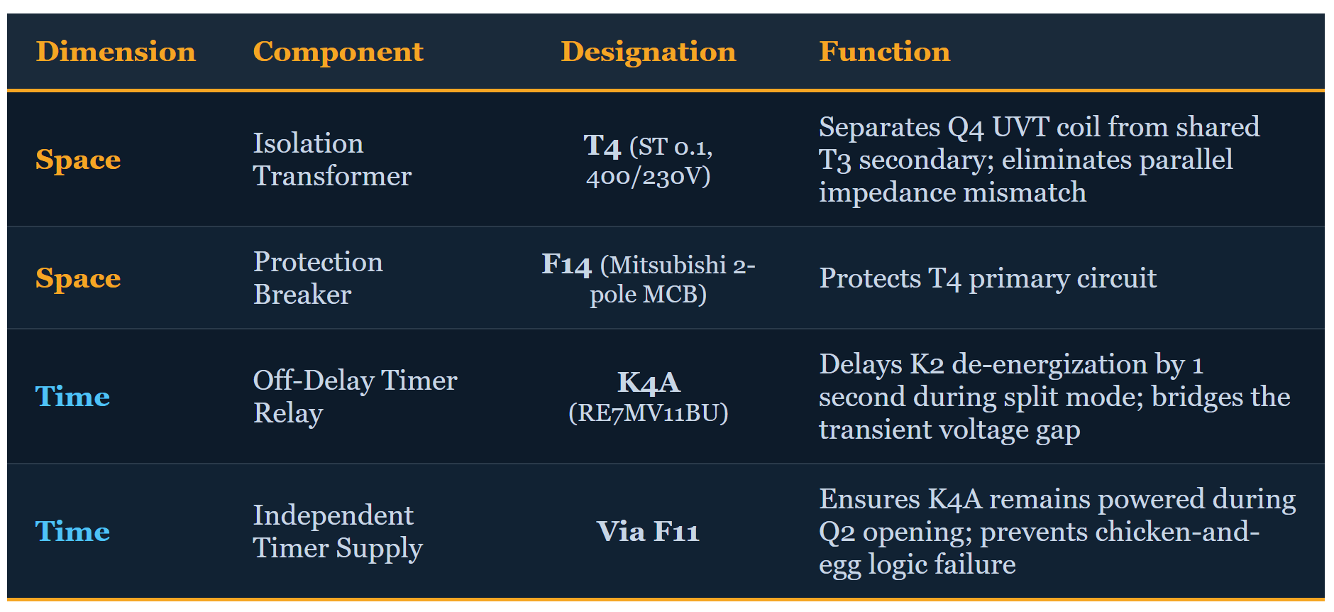
Result: After one full year of nuisance tripping on every split mode entry — zero trips following the Space-Time Jutsu installation.
Final Reflection: The Broader Lesson
We are surrounded by systems — power grids, industrial plants, ships, buildings — that are this messy mix of old and new technology. We are constantly plugging modern, digitally optimized components into old analog backbones and assuming they speak the same language. We assume backward compatibility.
But as this case study shows, a modern component might be better on paper — more efficient, faster, tighter tolerances — but its electrical personality might be totally incompatible with the old system’s habits. The new breaker was technically superior. But it was too fast, too sensitive for the old 28-year-old grid.
The ship had a certain rhythm. The new part was dancing to a completely different beat. We needed the timer to sync them up.
And here is one more thought that stayed with me long after the probe was closed: Remember those blowing fuses — F7/F8 and F9/F10? They were likely a symptom of hidden surges that nobody noticed for years. The redundancy masked it. The system compensated silently, eating fuses every now and then, and nobody connected the pattern to the switching transient because the old coils were forgiving enough to absorb it.
It took the installation of a modern, less-forgiving coil to expose what had been hiding in the circuit for potentially decades. The new breaker did not create the problem — it revealed the problem that was already there, buried under layers of redundancy and tolerance.
As we retrofit aging infrastructure — power grids, ships, factories — with modern, hyperfast, precision-engineered components, we will expose more of these hidden incompatibilities. Faults that current diagnostic tools cannot even see. Silent microsecond failures waiting for a modern, perfectly “equivalent” upgrade to bring the whole system down.
We may need a lot more Space-Time Jutsu in the future.
Sometimes the solution is not about working harder. It is about thinking in four dimensions. And always — always — updating your drawings.
Want the full technical PDF with 20+ real engine room photos, KCL equations, hand-drawn schematics, and the complete circuit diagrams?
📘 Get the ProbeStudy No. 03 PDF Mini eBook on Patreon →
The Patreon eBook includes everything you have read here plus: real engine room photos of every component mentioned (T3, T4, K4A, the relay bank, the fuse panels, the ring topology wiring), hand-drawn impedance analysis diagrams with KCL calculations, the complete before-and-after circuit schematics, and the full uncut 93-minute documentary version of Part 3 (YouTube Member exclusive).
If you found value in this case study, consider joining the probing cause. Every supporter helps build the digital library of real-world electrical troubleshooting knowledge — one probe at a time.
Keep on probing!
— Lem | ProbeLem
YouTube: @ProbeLem Substack: probelem.substack.com Facebook: ProbeLemSolving Patreon: patreon.com/ProbeLem
© 2026 ProbeLem. All rights reserved. PRObing Right into the Problem!
ProbeLem is a troubleshooting library built from real shipboard electrical work, diagnostics, and field reflection.
If this post helped, follow the blog for future case studies and leave a comment with the fault, system, or lesson you want explored next.

Comments
Post a Comment